S2EB-24V Panasonic Electric Works, S2EB-24V Datasheet - Page 4
S2EB-24V
Manufacturer Part Number
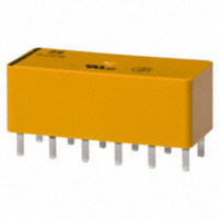
S2EB-24V
Description
RELAY POWER 4A 24VDC PCB
Manufacturer
Panasonic Electric Works
Series
Sr
Type
General Purpose Relayr
Specifications of S2EB-24V
Relay Type
General Purpose
Contact Form
4PST (2 Form A, 2 Form B)
Contact Rating (current)
4A
Switching Voltage
250VAC
Coil Type
Standard
Coil Current
8.4mA
Coil Voltage
24VDC
Turn On Voltage (max)
16.8 VDC
Turn Off Voltage (min)
2.4 VDC
Mounting Type
Through Hole
Termination Style
PC Pin
Circuit
4PST (2 Form A, 2 Form B)
Contact Rating @ Voltage
4A @ 250VAC
Control On Voltage (max)
16.8 VDC
Control Off Voltage (min)
2.4 VDC
Brand/series
S Series
Current, Rating
4⁄3 AAC⁄ADC
Diameter, Mounting
0.047 to 0.051 in.
Dimensions
1.102 in. L x 0.472 in. W x 0.409 in. H
Function
General Purpose
Latch Type
Single Side Stable
Material, Contact
Gold Clad Silver Alloy
Number Of Pins
12
Standards
UL, CSA
Temperature, Operating, Maximum
65 °C
Temperature, Operating, Minimum
-40 °C
Termination
Solder
Voltage, Control
24 VDC
Voltage, Rating
380 VAC
Relay Construction
Non-Latching
Contact Arrangement
DPST-NO/DPST-NC
Coil Voltage Dc
24V
Voltage Rating (vdc)
30V
Voltage Rating (vac)
250V
Dropout Volt (min)
2.4VDCV
Coil Resistance
2.85kohm
Pick-up Voltage (max)
16.8VDC
Maximum Power Rating
90W/1KVA
Operate Time
15ms
Contact Current Rating
3DC/4ACA
Contact Material
Silver(Cadmium Free)/Gold Clad
Coil Suppression Diode
No
Push To Test Button
No
Led Indicator
No
Seal
Unsealed
Product Height (mm)
10.4mm
Product Depth (mm)
12mm
Product Length (mm)
28mm
Operating Temp Range
-55C to 65C
Pin Count
12
Mounting Style
Through Hole
Package / Case
DIP
Lead Free Status / RoHS Status
Lead free / RoHS Compliant
Other names
255-1740
S2EB-24
S2EB-24V
S2EB-24
S2EB-24V
Available stocks
Company
Part Number
Manufacturer
Quantity
Price
Company:

Part Number:
S2EB-24V
Manufacturer:
FUJI
Quantity:
2 300


REFERENCE DATA
1. Maximum switching power
4.-(1) Coil temperature rise
Tested Sample: S4EB-24V, 4 Form A
6. Influence of adjacent mounting
8. Effect from an external magnetic field
1,000
100
100
(1)
10
90
80
70
60
50
40
30
20
10
0
+30
–30
+30
+30
–30
–30
0
0
0
(2)
Single side stable
Single side stable
2 coil latching
0.2
DC resistive load
(3)
0.1
Drop-out voltage
Pick-up voltage
0.4
Coil operating power, W
(1) & (3) relays
are energized
Inter-relay distance, mm
Contact current, A
0.6
50
50
5
Drop-out voltage
G
G
0.8
AC resistive load
1
Pick-up voltage
Pick-up voltage
1.0
Note: When installing an S-relay near another, and there is no effect
4A
0A
All Rights Reserved © COPYRIGHT Panasonic Electric Works Co., Ltd.
10
1.2
from an external magnetic field, be sure to leave at least 10 mm
.394 inch
listed in the catalog.
100
100
10
between relays in order to achieve the performance
+30
–30
2. Life curve
4.-(2) Coil temperature rise
Tested Sample: S4EB-24V, 4 Form A
0
2 coil latching
+30
–30
+30
–30
1,000
0
0
100
500
100
Single side stable
2 coil latching
50
30
10
90
80
70
60
50
40
30
20
10
0
0
Coil operating
power, 0.2 W
1
1
Pick-up voltage
Inter-relay distance, mm
5
2
2
Contact current, A
50
50
Contact current, A
G
G
3
3
Drop-out voltage
Pick-up voltage
Pick-up voltage
125 V AC
(cos = 1.0)
250 V AC
(cos = 1.0)
4
4
10
5
5
100
100
6
3. Contact reliability
Condition: 1V DC, 1mA
Detection level 10
Tasted Sample: S4EB-24V, 10pcs
5. Operate and release time
(Single side stable type)
Tested Sample: S4EB-24V, 10pcs
7. Thermal electromotive force
99.9
99.0
95.0
70.0
50.0
30.0
10.0
200
100
5.0
2.0
1.0
0.5
0.2
0.1
20
18
16
14
12
10
8
6
4
2
0
Max.
Min.
80
Release time
2
Release time (with diode)
4
100
No. of operations, 10
Coil applied voltage, %V
m = 1.6
95% reliability limit:
14.6 million times
(weibul probability paper)
: 79 million time
: 51 million time
1.0
NR-H
6
Minute
Operate time
120
NF relay S relay
8
10
140
7
Max.
Min.
Max.
Min.
10.0
12
S
Related parts for S2EB-24V
Image
Part Number
Description
Manufacturer
Datasheet
Request
R

Part Number:
Description:
RELAY POWER 4A 5VDC PCB
Manufacturer:
Panasonic Electric Works
Datasheet:
Part Number:
Description:
RELAY LATCH 4A 24VDC AMBER PCB
Manufacturer:
Panasonic Electric Works
Datasheet:
Part Number:
Description:
RELAY PWR LATCHING 4A 12VDC PCB
Manufacturer:
Panasonic Electric Works
Datasheet:
Part Number:
Description:
RELAY POWER LATCHING 4A 5VDC PCB
Manufacturer:
Panasonic Electric Works
Datasheet:
Part Number:
Description:
RELAY POWER 4A 12VDC PCB
Manufacturer:
Panasonic Electric Works
Datasheet:
Part Number:
Description:
RELAY 4A 3VDC AMBER SEALED PCB
Manufacturer:
Panasonic Electric Works
Datasheet:
Part Number:
Description:
RELAY 4A 6VDC AMBER SEALED PCB
Manufacturer:
Panasonic Electric Works
Datasheet:
Part Number:
Description:
RELAY LATCH 4A 3VDC AMBER PCB
Manufacturer:
Panasonic Electric Works
Datasheet:
Part Number:
Description:
RELAY LATCH 4A 12VDC AMBER PCB
Manufacturer:
Panasonic Electric Works
Datasheet:
Part Number:
Description:
RELAY LATCH 4A 6VDC AMBER PCB
Manufacturer:
Panasonic Electric Works
Datasheet:

Part Number:
Description:
CONN SOCKET P4 .4MM 50POS SMD
Manufacturer:
Panasonic Electric Works
Datasheet:

Part Number:
Description:
CONN SOCKET .8MM 16POS SMD
Manufacturer:
Panasonic Electric Works
Datasheet:
Part Number:
Description:
CONN HEADER .8MM 16POS SMD
Manufacturer:
Panasonic Electric Works
Datasheet:
Part Number:
Description:
CONN SOCKET .8MM 20POS SMD
Manufacturer:
Panasonic Electric Works
Datasheet:
Part Number:
Description:
CONN SOCKET .8MM 20POS SMD
Manufacturer:
Panasonic Electric Works
Datasheet: