G2R-1-S AC240(S) Omron, G2R-1-S AC240(S) Datasheet - Page 5
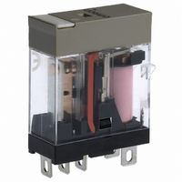
G2R-1-S AC240(S)
Manufacturer Part Number
G2R-1-S AC240(S)
Description
RELAY GP SPDT 240VAC PLUG-IN
Manufacturer
Omron
Series
G2RSr
Datasheets
1.G2R-1A-E-DC12.pdf
(30 pages)
2.G2R-1A-E-DC12.pdf
(14 pages)
3.G2R-1-S_DC12S.pdf
(12 pages)
Specifications of G2R-1-S AC240(S)
Relay Type
General Purpose
Contact Form
SPDT (1 Form C)
Contact Rating (current)
10A
Switching Voltage
440VAC, 125VDC - Max
Coil Type
Standard
Coil Current
3.2mA
Coil Voltage
240VAC
Turn On Voltage (max)
192 VAC
Turn Off Voltage (min)
72 VAC
Mounting Type
Socket
Termination Style
Quick Connect - .187" (4.7mm)
Circuit
SPDT (1 Form C)
Contact Rating @ Voltage
10A @ 250VAC
Control On Voltage (max)
192 VAC
Control Off Voltage (min)
72 VAC
Contact Rating
10 A
Contact Termination
Pin
Mounting Style
Plug-In
Power Consumption
0.9 VA
Contact Material
Silver Alloy
Coil Resistance
30.36 K Ohms
Lead Free Status / RoHS Status
Lead free / RoHS Compliant
Other names
G2R-1-S-AC240(S)
G2R-1S-AC240(S)
G2R1SAC240S
Z2227
G2R-1S-AC240(S)
G2R1SAC240S
Z2227


Moving Loop System
In the U.S.A., the National Association of Relay Manufactures
(NARM) in April 1984, awarded OMRON for monumental advances
in relay technology, as embodied in the Moving Loop System.
This unique relay construction maximizes electrical and permanent
magnet energy. A high-efficiency magnet adds to the magnetic flux of
the relay coil, which also allows for tighter packing of relay parts.
Relays having such a coil are known as “polarized relays.” Details of
construction are shown below.
The moving loop design has similarities with polarized relays; how-
ever, the following two features make for a large performance distinc-
tion.
A permanent magnet is placed in the vicinity of the “working gaps.”
The flux energy of this permanent magnet complements that of the
electrical coil. This increased efficiency enables the mechanism hold-
ing the contacts closed to ultimately switch larger loads, and at the
same time reduces the power consumed by the coil.
The following diagram shows concentric lines of magnetic flux when
the permanent magnet is placed near the working gap.
Conventional Relay Coil
The following diagram shows the lines of magnetic flux when the per-
manent magnet is placed away from the working gap. These lines of
flux detract from the total strength of the coil.
When the switching voltage is removed from the coil, the collapse of
the magnetic flux created by the permanent magnet and the electri-
cal coil provides the force to return the relay contacts to the reset
position. Note the flux path and magnet polarity in the illustration
overleaf.
Permanent
magnet
Core
Air gap
Core
Air gap
Armature
Air gap
Yoke
Permanent
magnet
Movable
contact
Permanent
magnet
Electromechanical Relays
Operating Principle, Moving Loop
Super Moving Loop System
A very small high-sensitivity magnetic circuit is incorporated to fur-
ther minimize the conventional moving loop system.
This magnetic circuit has the following features:
• High-efficiency polarized magnetic circuit utilizes power of both
• Balanced armature system improves resistance to both vibration
• Ideal mechanism for a low-profile relay.
Note: The above applies to a latching relay.
Release
Transition from
release to
operation
(operating voltage
supplied)
Operation
Release
Transition from
release to
operation
(operating voltage
supplied)
Operation
attraction and repulsion.
and impacts.
Core
Technical Information
Armature
Repulsion
Axis of
rotation
N
S
N
Permanent
magnet
S
S
S
N
N
Attraction
Repulsion
N
S
Attraction
N
S
Movement
Released status is
maintained by per
manent magnet.
Permanent
magnet
Energized status
is maintained by
the coil voltage
and permanent
magnet.
The armature see
saws due to the at
traction and repul
sion torque exerted
on the armature by
the coil voltage and
the permanent
magnet.
Coil
5
Related parts for G2R-1-S AC240(S)
Image
Part Number
Description
Manufacturer
Datasheet
Request
R

Part Number:
Description:
POWER RELAY, SPDT, 120VAC, 10A, PLUG IN
Manufacturer:
Omron
Datasheet:

Part Number:
Description:
Relay
Manufacturer:
Omron
Datasheet:

Part Number:
Description:
RELAY; E-MECH; POWER; SPDT; CUR-RTG 10A; CTRL-V 24DC; VOL-RTG 250/30AC/DC; SOCKET MNT
Manufacturer:
Omron Automation
Datasheet:
Part Number:
Description:
RELAY; E-MECH; POWER; SPDT; CUR-RTG 10A; CTRL-V 120AC; VOL-RTG 250/30AC/DC; SOCKET MNT
Manufacturer:
Omron Automation
Datasheet:
Part Number:
Description:
RELAY; E-MECH; POWER; SPDT; CUR-RTG 10A; CTRL-V 12DC; VOL-RTG 250/30AC/DC; SOCKET MNT
Manufacturer:
Omron Automation
Datasheet:
Part Number:
Description:
RELAY; E-MECH; POWER; SPDT; CUR-RTG 10A; CTRL-V 24AC; VOL-RTG 250/30AC/DC; SOCKET MNT
Manufacturer:
Omron Automation
Datasheet:
Part Number:
Description:
RELAY
Manufacturer:
Omron Automation
Datasheet:

Part Number:
Description:
Relay
Manufacturer:
Omron
Datasheet:
Part Number:
Description:
Relay
Manufacturer:
Omron
Datasheet:
Part Number:
Description:
Relay
Manufacturer:
Omron
Datasheet:
Part Number:
Description:
Relay
Manufacturer:
Omron
Datasheet:
Part Number:
Description:
Relay
Manufacturer:
Omron
Datasheet:
Part Number:
Description:
Relay
Manufacturer:
Omron
Datasheet:
Part Number:
Description:
Relay
Manufacturer:
Omron
Datasheet: