G7Z-4A-02Z DC24 Omron, G7Z-4A-02Z DC24 Datasheet - Page 7
G7Z-4A-02Z DC24
Manufacturer Part Number
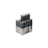
G7Z-4A-02Z DC24
Description
RELAY POWER 4PST 40A 24VDC
Manufacturer
Omron
Series
G7Zr
Datasheet
1.G7Z-2A2B-02Z_DC12.pdf
(10 pages)
Specifications of G7Z-4A-02Z DC24
Relay Type
General Purpose
Contact Form
4PST (4 Form A)
Contact Rating (current)
40A
Switching Voltage
480VAC - Max
Coil Type
Standard
Coil Current
154mA
Coil Voltage
24VDC
Turn On Voltage (max)
18 VDC
Turn Off Voltage (min)
2.4 VDC
Mounting Type
Chassis Mount
Termination Style
Screw Terminal
Circuit
4PST (4 Form A)
Contact Rating @ Voltage
40A @ 440VAC
Control On Voltage (max)
18 VDC
Control Off Voltage (min)
2.4 VDC
Contact Rating
40 A at 440 VAC
Contact Termination
Screw
Power Consumption
3.7 W
Lead Free Status / RoHS Status
Lead free / RoHS Compliant
Lead Free Status / RoHS Status
Lead free / RoHS Compliant, Lead free / RoHS Compliant
Other names
G7Z-4A-02ZDC24
G7Z4A02ZDC24
G7Z4A02ZDC24


Precautions
Be sure to read the common precautions provided in Best Control Devices Catalog Version 17 before using the Relay.
■ Precautions for Correct Use
Installation
• Mount the G7Z with the coil terminal at the top.
• Do not use the Relay with the terminal screw surfaces facing down.
• To mount the Relay, secure M4 screws in two locations. Use a
• The Relay can be mounted directly on a mounting rail (PTP) or a
Take measures to prevent contact with charged
parts when using the Relay for high voltages.
Do not touch the terminal section (charged parts)
when power is being supplied.
Always use the Relay with terminal covers
mounted. Contact with charged parts may result in
electric shock.
Do not touch the Relay when power is being sup-
plied or right after the power has been turned OFF.
The hot surface may cause burn injury.
screw-tightening torque of 1.2 to 1.3 N•m.
DIN Track (EN 50022-35 x 7.5, 15). The Relay cannot be mounted,
however, to some reinforced rails (e.g., those produced by Kameda
Denki or Toyogiken).
!CAUTION
!WARNING
Terminal screw surface
Washer (external dia.: 7 max.)
Up
Coil terminal
39 mm
• Mount the Relay sideways when it is mounted on a rail.
• Use End Plates (PFP-M) on both sides of the Relay to make sure
• Provide at least 5 mm of space between the sides and top of the
• Provide at least 30 mm of space between Relays when two or more
• The auxiliary contact block (G73Z) can be mounted on the Relay.
Mounting and Removal
Mounting
Insert the tab on the auxiliary contact
block into the groove on the Relay and
press down until the hook on the auxil-
iary contact block catches in the
mounting hole on the Relay.
Removing
Slide the auxiliary contact block,
remove the auxiliary contact block tab
from the groove on the Relay, and
remove the auxiliary contact block
hook from the Relay.
Be careful not to apply excessive force
on the hook.
that it is properly secured.
Relay and nearby grounded metal surfaces.
Relays are mounted in a row.
Grounded metal surface
Power Relays
Up
30 mm min.
5 mm min.
Hook
Hook
5 mm min.
(2)
(1)
G7Z
5 mm min.
DIN Track
(35 mm)
335
(1)
Tab
Tab
(2)
Related parts for G7Z-4A-02Z DC24
Image
Part Number
Description
Manufacturer
Datasheet
Request
R

Part Number:
Description:
Heavy Duty Relay
Manufacturer:
Omron
Datasheet:

Part Number:
Description:
Heavy Duty Relay
Manufacturer:
Omron
Datasheet:
Part Number:
Description:
Heavy Duty Relay
Manufacturer:
Omron
Datasheet:
Part Number:
Description:
Heavy Duty Relay
Manufacturer:
Omron
Datasheet:

Part Number:
Description:
Heavy Duty Relay
Manufacturer:
Omron
Datasheet:


Part Number:
Description:
G6S-2GLow Signal Relay
Manufacturer:
Omron Corporation
Datasheet:
Part Number:
Description:
Compact, Low-cost, SSR Switching 5 to 20 A
Manufacturer:
Omron Corporation
Datasheet:
Part Number:
Description:
Manufacturer:
Omron Corporation
Datasheet: