G7Z-4A-02Z DC24 Omron, G7Z-4A-02Z DC24 Datasheet - Page 8
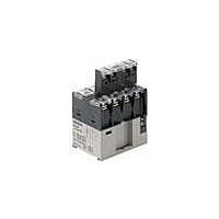
G7Z-4A-02Z DC24
Manufacturer Part Number
G7Z-4A-02Z DC24
Description
RELAY POWER 4PST 40A 24VDC
Manufacturer
Omron
Series
G7Zr
Datasheet
1.G7Z-2A2B-02Z_DC12.pdf
(10 pages)
Specifications of G7Z-4A-02Z DC24
Relay Type
General Purpose
Contact Form
4PST (4 Form A)
Contact Rating (current)
40A
Switching Voltage
480VAC - Max
Coil Type
Standard
Coil Current
154mA
Coil Voltage
24VDC
Turn On Voltage (max)
18 VDC
Turn Off Voltage (min)
2.4 VDC
Mounting Type
Chassis Mount
Termination Style
Screw Terminal
Circuit
4PST (4 Form A)
Contact Rating @ Voltage
40A @ 440VAC
Control On Voltage (max)
18 VDC
Control Off Voltage (min)
2.4 VDC
Contact Rating
40 A at 440 VAC
Contact Termination
Screw
Power Consumption
3.7 W
Lead Free Status / RoHS Status
Lead free / RoHS Compliant
Lead Free Status / RoHS Status
Lead free / RoHS Compliant, Lead free / RoHS Compliant
Other names
G7Z-4A-02ZDC24
G7Z4A02ZDC24
G7Z4A02ZDC24


Connecting
• Use round or open-end (Y-type) crimp terminals and connect the
Relay Contacts (Unit: mm)
Relay Coil
Auxiliary Contact Block
• One crimp terminal can be used for the Relay contact section (M5
Recommended Crimp Terminals and Wire
• Use the following tightening torque when tightening screws. Loose
• Allow suitable slack on leads when wiring, and do not subject the
Microloads
The G7Z is used for switching power loads, such as current carry for
device power supplies and heater loads. Use an auxiliary contact
block (G73Z) if microloads are required for signal applications and
operation status feedback.
336
Contact
section
Coil section 1.25-3.5
terminals with the appropriate tightening torque. Refer to the termi-
nal section space in the following figure for the crimp terminal
dimensions.
screw). Two crimp terminals can be connected for the coil terminal
and auxiliary contact block.
screws may result in fire caused by abnormal heat generated when
the power is being supplied.
M5 screws: 2.0 to 2.2 N•m
M3.5 screws: 0.8 to 0.9 N•m
terminals to excessive force.
Location
5.5-5
8-5
Power Relays
6
6
terminals
12.5
Crimp
5.5
5.5
6.8
2.63 to 6.64 mm
6.64 to 10.52 mm
0.5 to 1.65 mm
4.3
14.5
9.5
G7Z
Appropriate wire size
6.8
M3.5
M5
2
M3.5
2
(AWG20 to 16)
2
(AWG12, 10)
11
(AWG8)
Operating Coil
(Internal Connections of Coils)
DC Coil
• If a transistor drives the G7Z, check the leakage current and con-
• The must operate voltage is the minimum value for the Relay arma-
Mirror Contact Mechanism
By combining a Relay with an auxiliary contact block, all NC contacts
of the auxiliary contact block will satisfy an impulse withstand voltage
of more than 2.5 kV or maintain a gap of more than 0.5 mm when the
coil is de-energized even if at least one NO contact (main contact) of
the Relay is welded (according to EN 60947-4-1).
Description of Mirror Contact Mechanism
nect a bleeder resistor if necessary.
ture to operate and the contacts to turn ON. Therefore, fundamen-
tally apply the rated voltage to the coils, taking into consideration
the increases in coil resistance caused by voltage fluctuation and
coil temperature rise.
Contact welding
A2
Impulse withstand voltage: 2.5 kV min. or
contact separation (a + b): 0.5 mm min.
a
NO
NC
b
NO
Auxiliary contact block
NC
NO
A1
NO
Relay
Related parts for G7Z-4A-02Z DC24
Image
Part Number
Description
Manufacturer
Datasheet
Request
R

Part Number:
Description:
Heavy Duty Relay
Manufacturer:
Omron
Datasheet:

Part Number:
Description:
Heavy Duty Relay
Manufacturer:
Omron
Datasheet:
Part Number:
Description:
Heavy Duty Relay
Manufacturer:
Omron
Datasheet:
Part Number:
Description:
Heavy Duty Relay
Manufacturer:
Omron
Datasheet:

Part Number:
Description:
Heavy Duty Relay
Manufacturer:
Omron
Datasheet:


Part Number:
Description:
G6S-2GLow Signal Relay
Manufacturer:
Omron Corporation
Datasheet:
Part Number:
Description:
Compact, Low-cost, SSR Switching 5 to 20 A
Manufacturer:
Omron Corporation
Datasheet:
Part Number:
Description:
Manufacturer:
Omron Corporation
Datasheet: