G6L-1P-DC4.5 Omron, G6L-1P-DC4.5 Datasheet - Page 2
G6L-1P-DC4.5
Manufacturer Part Number
G6L-1P-DC4.5
Description
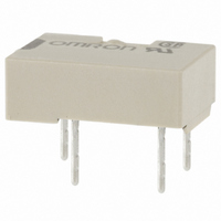
RELAY TELCOM SPST 4.5VDC PC MNT
Manufacturer
Omron
Series
G6Lr
Specifications of G6L-1P-DC4.5
Coil Type
Standard
Coil Current
40mA
Relay Type
Telecom
Circuit
SPST-NO (1 Form A)
Contact Rating @ Voltage
1A @ 24VDC
Coil Voltage
4.5VDC
Control On Voltage (max)
3.38 VDC
Control Off Voltage (min)
0.45 VDC
Mounting Type
Through Hole
Termination Style
PC Pin
Contact Form
1 Form C
Power Consumption
180 mW
Maximum Switching Current
1 A
Contact Rating
0.3 A at 125 VAC, 1 A at 24 VDC
Contact Configuration
SPST-NO
Contact Current Max
1A
Contact Voltage Ac Nom
125V
Contact Voltage Dc Nom
24V
Coil Voltage Vdc Nom
4.5V
Current, Rating
0.3⁄1 AAC⁄ADC
Dielectric Rating
1000 VAC @ 50⁄60 Hz for 1 Minute (Coil and Contacts), 750 VAC @ 50⁄60 Hz for 1 Minute (Contacts of Same Poles)
Dimensions
10.6 mm L x 7 mm W x 3.8 mm H
Function
General Purpose
Material, Contact
Ag (Au-Clad)
Number Of Pins
4
Standards
UL, CSA, FCC, RoHS
Temperature, Operating, Maximum
70 °C
Temperature, Operating, Minimum
-40 °C
Termination
Through Hole
Voltage, Control
4.5 VDC
Voltage, Rating
125 VAC
Lead Free Status / RoHS Status
Lead free / RoHS Compliant
Lead Free Status / RoHS Status
Lead free / RoHS Compliant, Lead free / RoHS Compliant
Other names
G6L1PDC4.5
G6L1PDC45
Z1227
G6L1PDC45
Z1227
Available stocks
Company
Part Number
Manufacturer
Quantity
Price
Company:

Part Number:
G6L-1P-DC4.5V
Manufacturer:
FUJITSU
Quantity:
12 000


Specifications
■ Contact Ratings
Note: This value was measured at a switching frequency of 120 operations/min. This value may vary, depending on switching frequency, operating
■ Coil Ratings
Note: 1. The rated current and coil resistance are measured at a coil temperature of 23°C with a tolerance of ±10%.
■ Characteristics
Note: 1. The contact resistance was measured with 10 mA at 1 VDC with a fall-of-potential method.
38
Contact mechanism
Rated load
Carry current
Max. operating voltage
Max. operating current
Min. permissible load - P level (See note)
Rated voltage
Rated current
Coil resistance
Pick-up voltage
Dropout voltage
Maximum voltage
Power consumption
Contact resistance (See Note 1)
Operate time (See Note 2)
Release time (See Note 2)
Insulation resistance (See Note 3)
Dielectric strength
Surge withstand
voltage
Vibration
Shock
Service life
Ambient temperature
Humidity
Weight
conditions, expected reliability level of the relay, etc. It is always recommended to double-check relay suitability under actual load conditions.
2. The operating characteristics are measured at a coil temperature of 23°C.
3. The maximum voltage is the highest voltage that can be imposed on the relay coil.
4. The voltage measurements for Pick-up/Dropout are the values obtained for instantaneous changes in the voltage (rectangular wave).
2. Values in parentheses are actual values.
3. The insulation resistance was measured with a 500-VDC megohmmeter applied to the same parts as those used for checking the dielec-
4. The above values are initial values.
tric strength.
Item
Low Signal Relay
Item
Coil and contacts
Contacts of same
poles
Coil and contacts
Mechanical durability
Malfunction durability 10 to 55 Hz, 1.65-mm single amplitude (3.3-mm double amplitude)
Mechanical durability
Malfunction durability 100 m/s
Mechanical
Electrical
Item
3 VDC
60.0 mA
50.0 Ω
75% max. of rated voltage
10% min. of rated voltage
150% of rated voltage
Approx. 180 mW
G6L
100 mΩ max.
5 ms max. (approx. 1.1 ms)
5 ms max. (approx. 0.4 ms)
1,000 MΩ min. (at 500 VDC)
1,000 VAC, 50/60 Hz for 1 min
750 VAC, 50/60 Hz for 1 min
1,500 VAC, 10 × 160 μs
10 to 55 Hz, 1.65-mm single amplitude (3.3-mm double amplitude)
1,000 m/s
5,000,000 operations min. (at 36,000 operations/hour)
100,000 operations min. (with a rated load at 1,800 operations/hour)
Operating: -40°C to 70°C (with no icing or condensation)
Operating: 5% to 85% RH
Approx. 0.6 g
4.5 VDC
40.0 mA
112.5 Ω
Single crossbar
0.3 A at 125 VAC, 1 A at 24 VDC
1 A
125 VAC, 60 VDC
1 A
1 mA at 5 VDC
2
2
5 VDC
36.0 mA
139.0 Ω
Voltage Rating
G6L-1P, G6L-1F
Resistive load
12 VDC
15.0 mA
800.0 Ω
24 VDC
9.6 mA
2,504.0 Ω
130% of rated
voltage
Approx. 230 mW
Related parts for G6L-1P-DC4.5
Image
Part Number
Description
Manufacturer
Datasheet
Request
R

Part Number:
Description:
LOW SIGNAL RELAY
Manufacturer:
Omron
Datasheet:
Part Number:
Description:
LOW SIGNAL RELAY
Manufacturer:
Omron
Datasheet:

Part Number:
Description:
Low Signal Relays - PCB LO PROF SPST 5VDC
Manufacturer:
Omron
Datasheet:
Part Number:
Description:
Low Signal Relays - PCB LO PROF SPST 12VDC
Manufacturer:
Omron
Datasheet:
Part Number:
Description:
RELAY TELCOM SPST 3VDC PC MNT
Manufacturer:
Omron
Datasheet:
Part Number:
Description:
RELAY TELCOM SPST 24V PCB
Manufacturer:
Omron
Datasheet:

Part Number:
Description:
RELAY, PCB, SPNO, 24VDC
Manufacturer:
Omron
Datasheet:
Part Number:
Description:
RELAY, PCB, SPNO, 3VDC
Manufacturer:
Omron
Datasheet:
Part Number:
Description:
RELAY, PCB, SPNO, 5VDC
Manufacturer:
Omron
Datasheet:

Part Number:
Description:
RELAY, SMD, SPNO, 12VDC
Manufacturer:
Omron
Datasheet: