G3VM-41GR5 Omron, G3VM-41GR5 Datasheet - Page 2
G3VM-41GR5
Manufacturer Part Number
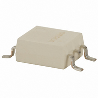
G3VM-41GR5
Description
RELAY SSR SPST 40VAC 300MA 4SOP
Manufacturer
Omron
Series
G3VMr
Specifications of G3VM-41GR5
Load Current
300mA
Circuit
SPST-NO (1 Form A)
Output Type
AC, DC
On-state Resistance
1.5 Ohm
Voltage - Input
1.15VDC
Voltage - Load
0 ~ 40 V
Mounting Type
Surface Mount
Termination Style
Gull Wing
Package / Case
4-SOP
Control Voltage Range
1 V to 1.3 V
Load Voltage Rating
40 V
Off State Leakage Current (max)
1 nA
Load Current Rating
300 mA
Contact Form
1 Form A
Output Device
MOSFET
Mounting Style
SMD/SMT
Relay Type
MOSFET Relay
Turn-on Switching
FET
Load Voltage Max
40VAC
On State Resistance Max
1.5ohm
Contact Configuration
SPST-NO
Isolation Voltage
1500Vrms
Forward Current If
30mA
Relay Terminals
SMD
No. Of Pins
4
Rohs Compliant
Yes
Lead Free Status / RoHS Status
Lead free / RoHS Compliant
Lead Free Status / RoHS Status
Lead free / RoHS Compliant, Lead free / RoHS Compliant
Other names
G3VM41GR5
Z2078
Z2078
Available stocks
Company
Part Number
Manufacturer
Quantity
Price
Company:

Part Number:
G3VM-41GR5
Manufacturer:
OMRON
Quantity:
12 000
Part Number:
G3VM-41GR5
Manufacturer:
OMRON/欧姆龙
Quantity:
20 000
Company:
Part Number:
G3VM-41GR5(TR)
Manufacturer:
OMRON
Quantity:
12 000


Precautions
2
Be sure to turn OFF the power when wiring the Relay, otherwise
an electric shock may be received.
Do not touch the charged terminals of the SSR, otherwise an elec-
tric shock may be received.
Do not apply overvoltage or overcurrent to the I/O circuits of the
SSR, otherwise the SSR may malfunction or burn.
Be sure to wire and solder the Relay under the proper soldering
conditions, otherwise the Relay in operation may generate exces-
sive heat and the Relay may burn.
Electrostatic sensitive devices. Keep in original packaging until re-
quired to use. Avoid touching device terminals. Take static han-
dling precautions during processing.
!CAUTION
!CAUTION
!CAUTION
!WARNING
!WARNING
OMRON logo
OMRON logo
MOS FET Relays
DIP (Dual Inline Package)
SOP (Small Outline Package)
SSOP (Shrink Small Outline Package)
OMRON mark
Note: "G3VM" is not printed on the
Appearance Examples
actual product.
211
228
Technical Information
Model name
LOT No.
Model name
LOT No.
Model name
LOT No.
Use the following formula to obtain the LED current limiting resis-
tance value to assure that the relay operates accurately.
Use the following formula to obtain the LED forward voltage value to
assure that the relay releases accurately.
■ Protection from Surge Voltage on the
If any reversed surge voltage is imposed on the input terminals,
insert a diode in parallel to the input terminals as shown in the follow-
ing circuit diagram and do not impose a reversed voltage value of 3 V
or more.
Input Terminals
C-MOS
Transistor
Surge Voltage Protection Circuit Example
10 to 100 kΩ
Typical Relay Driving Circuit Examples
R
V
1
F (OFF)
=
V
= V
CC
5 to 20 mA
− V
CC
− V
OL
− V
OH
F
< 0.8 V
(ON)
Load
Load
Related parts for G3VM-41GR5
Image
Part Number
Description
Manufacturer
Datasheet
Request
R

Part Number:
Description:
RELAY SSR SPST 150MA 4-SOP
Manufacturer:
Omron
Datasheet:

Part Number:
Description:
RELAY SSR SPST 120MA 4-SOP
Manufacturer:
Omron
Datasheet:
Part Number:
Description:
RELAY SSR SPST 60V 400MA 4SOP
Manufacturer:
Omron
Datasheet:

Part Number:
Description:
SSR, MOSFET, 350V, 100mA
Manufacturer:
Omron
Datasheet:

Part Number:
Description:
Relay (Solid-State)
Manufacturer:
Omron
Datasheet:
Part Number:
Description:
Relay (Solid-State)
Manufacturer:
Omron
Datasheet:
Part Number:
Description:
MOSFET SSOP Tape&Reel - 500pcs
Manufacturer:
Omron
Datasheet:
Part Number:
Description:
MOSFET SSOP Tape & Reel-500pcs
Manufacturer:
Omron
Datasheet:
Part Number:
Description:
RELAY SSR SPST 60V 1A 4-SOP
Manufacturer:
Omron
Datasheet:

Part Number:
Description:
4-PIN Dip SMT MOSFET Relay
Manufacturer:
Omron
Datasheet:
Part Number:
Description:
SOP-4 1A MOSFET Relay
Manufacturer:
Omron
Datasheet:
Part Number:
Description:
SOP-4 1A MOSFET Relay
Manufacturer:
Omron
Datasheet:
Part Number:
Description:
4-Pin Dip SMT MOS FET Relay
Manufacturer:
Omron
Datasheet:

Part Number:
Description:
4-Pin SSOP MOSFET Relay
Manufacturer:
Omron
Datasheet:

Part Number:
Description:
SOP-4 1A MOSFET Relay
Manufacturer:
Omron
Datasheet: