DC-2R5E224U-E Elna America, DC-2R5E224U-E Datasheet - Page 140
DC-2R5E224U-E
Manufacturer Part Number
DC-2R5E224U-E
Description
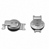
CAP DOUBLE LAYER .22F 2.5V COIN
Manufacturer
Elna America
Series
DCr
Specifications of DC-2R5E224U-E
Capacitance
220mF
Voltage - Rated
2.5V
Tolerance
-20%, +80%
Esr (equivalent Series Resistance)
100.00 Ohm
Lifetime @ Temp.
1000 Hrs @ 70°C
Mounting Type
Surface Mount
Package / Case
Surface Mount - Coin Style
Lead Spacing
0.079" (2.00mm)
Height
0.295" (7.50mm)
Size / Dimension
0.268" Dia (6.80mm)
Operating Temperature
-25°C ~ 70°C
Lead Free Status / RoHS Status
Lead free / RoHS Compliant
Other names
604-1006


1-4 Construction of DYNACAP
The basic cell construction of the DB, DBN, DX,
DXJ, DH, DK, DBJ, DC, DCK, DS, and DSK series is
similar to that of coin-type batteries as shown in Fig.2.
DYNACAP contains a single cell or two to three cells
stacked in series.
Since these series have a large electrode-to-electrode
distance and a small electrode area exhibiting a large
internal resistance, they are suitable for the memory
backup
discharge.
The cylindrical cell construction as seen in the DZ and
DZN series has the construction similar to that of
aluminum electrolytic capacitors as shown in Fig.3.
NOTE
Design, Specifications are subject to change without notice.
Ask factory for technical specifications before purchase and/or use.
Fig.3 Example of Basic Construction of Cylindrical Cell
Fig.2 Example of Basic Construction of Coin Cell
Activated carbon
Gasket
electrode
Aluminum
application
case
®
Electrolyte
Separator
that
involves
Seal rubber
LAYER CAPACITORS
ELECTRIC DOUBLE
Terminal
Cap
Case
Separator
Activated carbon
microcurrent
electrode
TECHNICAL NOTE
These series have a small electrode-to-electrode
distance, allowing a large electrode area because of
the winding structure. This decreases the internal resis-
tance, which is primary suitable for applications requir-
ing high-power such as motor drive and LED Iighting
that need high currents.
2 Description of Life Expectancy
Generally, the life of Electric Double Layer Capacitors is
largely affected by the ambient temperature.
The expected life is approximated by the equation as
shown below:
Note that the above equation does not cover charge
and discharge. In the case of charge and discharge,
heat generation occurs inside a capacitor; the
temperature rise by this heat generation must also be
considered.
L = L
Where,
0
×2
L : Expected lifetime at temperature T
L
T : Expected working temperature
T
)
0
0
T
: Lifetime at temperature T
: Upper category temperature
0
−T
10
)
CAT.No.2008/2009E ( 2008.10.1 )
0
Related parts for DC-2R5E224U-E
Image
Part Number
Description
Manufacturer
Datasheet
Request
R

Part Number:
Description:
IC H-BRIDGE 7A DC MOTOR PDSO-20
Manufacturer:
Infineon Technologies
Datasheet:

Part Number:
Description:
DC 38..75Vi>15Vo 6.6A 99W
Manufacturer:
Power-One
Datasheet:

Part Number:
Description:
DC/DC Converters & Regulators 48W 24V 2A
Manufacturer:
POWER ONE

Part Number:
Description:
CONV DC-DC 50W 24VDC CASSETTE
Manufacturer:
POWER ONE
Datasheet:


Part Number:
Description:
CAP DOUBLE LAYER .10F 5.5V COIN
Manufacturer:
Elna America
Datasheet:

Part Number:
Description:
Supercapacitors V/MOUNT 5.5V 0.1F
Manufacturer:
Elna America
Datasheet:

Part Number:
Description:
CAP DOUBLE LAYER .07F 3.3V COIN
Manufacturer:
Elna America
Datasheet:

Part Number:
Description:
Vertical Chip Type Aluminum Electrolytic Capacitors
Manufacturer:
ELNA America, Inc.
Datasheet: