F3C-AL14-M1J 0.2M Omron, F3C-AL14-M1J 0.2M Datasheet - Page 7
F3C-AL14-M1J 0.2M
Manufacturer Part Number
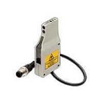
F3C-AL14-M1J 0.2M
Description
SENSOR LASER PHOTOELECTRIC NPN
Manufacturer
Omron
Specifications of F3C-AL14-M1J 0.2M
Lead Free Status / RoHS Status
Lead free / RoHS Compliant
Other names
F3C-AL14-M1J0.2M
F3CAL14M1J02M
F3CAL14M1J02M


Design
Power Reset Time
The Photoelectric Sensor is ready to sense an object in 300
ms after power-on. Therefore, use it 300 ms after power-on. If
the load and Sensor are connected to different power sup-
plies, always switch on power for the Sensor first.
Wiring Considerations
Load short-circuit protection
Dimensions (Unit: mm)
Sensors
F3C-AL14-M1J
F3C-AL44-M1J
Accessories (Order Separately)
Mounting Brackets
A-314
A-254
• The F3C-AL has load short-circuit protection. If a load short-
• Do not use the input power exceeding the rated voltage. Do-
• Do not shorten the load with the open collector output. Oth-
• Run the wiring of F3C separately from the high voltage and
• Avoid wiring them together or running them within the same
• For extension of the cable, use a 0.3-mm
circuit or like has occurred, the output turns OFF. Therefore,
recheck the wiring and switch power on again. This resets
the short-circuit protection circuit. Load short-circuit protec-
tion is activated when a current of 1.8 times or more of the
rated load current flows. When using an L load, use the one
the inrush current of which is less than 1.8 times of the rated
load current.
ing so can cause damage.
erwise, damage might be caused.
power cables.
duct. Doing so may get them induced, causing a malfunc-
tion or damage.
and run it within 50 m.
Correct Use
Receiver
2
Emitter
4.7
or more cable
(55)
8
90
4
4
42
18
Stability indicator (green)
Three,
4.2 dia.
Light indicator (red)
32
Distance adjuster
Mounting
Miscellaneous
Operating Environment
• Install the photoelectric sensor so that the sun, fluorescent
• If Sensors are installed face-to-face, ensure that no optical
• Use M4 screws to mount the unit.
• When mounting the case tighten it to the torque of 1.2 Nm
• Avoid using the Sensor in a strong disturbance light (e.g. la-
• Depending on their material and/or shape, some objects
37
45
lamp, incandescent lamp or any other strong light will not
enter the directional angle range of the sensor.
axes cross each other. Otherwise, mutual interference may
result.
max.
ser beam or arc welding beam) or strong electromagnetic
field.
may not be detected or may be detected with low accuracy.
(Mirror-smooth material, transparent material, material of
extremely low reflectivity, object smaller than spot diameter)
Note. L-ON when 1-2 are connected
Note: Connection 1 to 2 is L-ON
Terminal No.
inyl-insulated round cable of 4 dia.
4 cores conductorStandard length:
200 mm
nal No.
Termi-
1
2
3
4
1
2
3
4
Connection 2 to 3 is D-ON
D-ON when 2-3 are connected
L-ON/D-ON selectable
Specifications
Output
Specifications
L-ON/D-ON
+V
0V
selection
Output
Photoelectric Sensors
+V
0V
CAD file
M12
x
1
1
2
F3C_01
4
3
Related parts for F3C-AL14-M1J 0.2M
Image
Part Number
Description
Manufacturer
Datasheet
Request
R

Part Number:
Description:
G6S-2GLow Signal Relay
Manufacturer:
Omron Corporation
Datasheet:
Part Number:
Description:
Compact, Low-cost, SSR Switching 5 to 20 A
Manufacturer:
Omron Corporation
Datasheet:
Part Number:
Description:
Manufacturer:
Omron Corporation
Datasheet:
Part Number:
Description:
Manufacturer:
Omron Corporation
Datasheet:
Part Number:
Description:
Manufacturer:
Omron Corporation
Datasheet:
Part Number:
Description:
Manufacturer:
Omron Corporation
Datasheet:
Part Number:
Description:
Manufacturer:
Omron Corporation
Datasheet:
Part Number:
Description:
Manufacturer:
Omron Corporation
Datasheet: