RPER71H153K2P1A03B Murata Electronics North America, RPER71H153K2P1A03B Datasheet - Page 16
RPER71H153K2P1A03B
Manufacturer Part Number
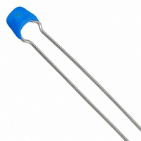
RPER71H153K2P1A03B
Description
CAP CER 15000PF 50V X7R RADIAL
Manufacturer
Murata Electronics North America
Series
RPEr
Datasheets
1.RPEF51H104Z2K1A03B.pdf
(2 pages)
2.RPEF51H104Z2K1A03B.pdf
(23 pages)
3.RPEF51H104Z2K1A03B.pdf
(3 pages)
4.RPER71H153K2P1A03B.pdf
(1 pages)
Specifications of RPER71H153K2P1A03B
Capacitance
0.015µF
Voltage - Rated
50V
Tolerance
±10%
Temperature Coefficient
X7R
Mounting Type
Through Hole
Operating Temperature
-55°C ~ 125°C
Applications
General Purpose
Package / Case
Radial
Size / Dimension
0.138" L x 0.197" W (3.50mm x 5.00mm)
Thickness
2.50mm Max
Lead Spacing
0.098" (2.50mm)
Lead Style
Kinked
Lead Free Status / RoHS Status
Lead free / RoHS Compliant
Features
-
Ratings
-
Other names
490-3818


!Note
!Note
No.
1
2
3
4
5
6
7
8
9
Operating Temperature
Range
Rated Voltage
Appearance
Dimension and Marking
Dielectric
Strength
Insulation
Resistance
Capacitance
Q/Dissipation Factor (D.F.)
Capacitance
Temperature
Characteristics
• Please read rating and !CAUTION (for storage and operating, rating, soldering and mounting, handling) in this catalog to prevent smoking and/or burning, etc.
• This catalog has only typical specifications because there is no space for detailed specifications. Therefore, please approve our product specification or transact the approval sheet for product specification before ordering.
Please read rating and !CAUTION (for storage and operating, rating, soldering and mounting, handling) in this PDF catalog to prevent smoking and/or burning, etc.
This catalog has only typical specifications. Therefore, you are requested to approve our product specification or to transact the approval sheet for product specificaion before ordering.
Item
Between
Terminals
Body
Insulation
Between
Terminals
Capacitance
Change
Temperature
Coefficient
Capacitance
Drift
Temperature Compensating Type High Dielectric Constant Type
Y55 to W125˚C
See previous pages.
No defects or abnormalities.
See Dimensions
No defects or abnormalities.
No defects or abnormalities.
100,000MΩ min. or 1000Ω • F
min. (whichever is smaller)
Within the specified tolerance.
30pF min. : Q U 1000
30pF max. : Q U 400W20C
C : Nominal capacitance (pF)
Within the specified tolerance.
(Table A)
Within the specified tolerance.
(Table A)
Within T0.2% or T0.05pF
(Whichever is larger)
Specification
X7R : Y55 to W125˚C
Z5U : W10 to W185˚C
Y5V : Y30 to W185˚C
X7R : 100,000MΩ min. or 1000Ω • F min.
Z5U
Y5V
X7R
Z5U
Y5V : 0.05 max.
Within the specified tolerance.
(Table B)
}
}
:
: 0.025 max.
(whichever is smaller)
10,000MΩ min. or 500Ω • F min.
(whichever is smaller)
Specifications and Test Methods
The rated voltage is defined the maximum voltage
which may be applied continously to the capacitor.
When AC voltage is superimposed on DC voltage, V
or V
the rated voltage range.
Visual inspection.
Visual inspection. Vernier Caliper.
The capacitors shall not be damaged when DC
voltages of 300 % of the rated voltage are applied
between the terminals for 1 to 5 seconds.
(Charge/discharge current V 50mA)
The capacitor is placed in a
container with metal balls of
diameter 1mm so that each
terminal, short-circuited, is kept
approximately 2mm from the balls
as shown in the figure, and 250 %
of the rated DC voltage is
impressed for one to five seconds
between capacitor terminals and
metal balls. (Charge/discharge
current V 50mA)
The insulation resistance shall be measured with a DC
voltage not exceeding the rated voltage at normal
temperature and humidity and within 2 minutes of
charging. (Charge/Discharge current V 50mA)
The capacitance, Q/DF shall be measured at 25˚C at
the frequency and voltage shown in the table.
The capacitance change shall be measured after 5min.
at each specified temperature stage.
(1) Temperature Compensating Type
The temperature coefficient is determined using the
capacitance measured in step 3 as a reference. When
cycling the temperature sequentially from step 1
through 5 (Y55 to W125˚C for C0G ; Y55 to W85˚C for
other temp. coeffs.) the capacitance shall be within the
specified tolerance for the temperature coefficient and
capacitance change as Table A. The capacitance drift
is caluculated by dividing the differences between the
maximum and minimum measured values in step 1, 3
and 5 by the cap. value in step 3.
(2) High Dielectric Constant Type
The ranges of capacitance change compared with the
25˚C value over the temperature ranges shown in the
Table B shall be within the specified ranges.
Item
Frequency
O-P
Voltage
, whichever is larger, shall be maintained within
Step
Char.
1
2
3
4
5
0.5 to 5Vrms 1T0.2Vrms 0.5T0.0.5Vrms
C0G, R2H, U2J
1T0.1MHz
(1000pF and
Below)
Test Method
Continued on the following page.
85T3 (for other TC)
Temperature (˚C)
C0G, R2H, U2J
125T3 (for C0G)
1T0.1kHz
(more than
X7R, Y5V)
1000pF)
Y25T2
Y55T3
Y25T2
Y25T2
C49E14.pdf 02.9.17
1T0.1kHz
Approx. 2mm
Z5U
Metal balls
P-P
15
1
Related parts for RPER71H153K2P1A03B
Image
Part Number
Description
Manufacturer
Datasheet
Request
R

Part Number:
Description:
BUZZER PIEZO 25VP-P SMD
Manufacturer:
Murata Electronics North America

Part Number:
Description:
CAP 4-ARRAY 680PF 100V X7R 1206
Manufacturer:
Murata Electronics North America
Datasheet:
Part Number:
Description:
CAP 4-ARRAY 1000PF 100V X7R 1206
Manufacturer:
Murata Electronics North America
Datasheet:
Part Number:
Description:
CAP 4-ARRAY 1800PF 100V X7R 1206
Manufacturer:
Murata Electronics North America
Datasheet:
Part Number:
Description:
CAP 4-ARRAY 68000PF 16V X7R 1206
Manufacturer:
Murata Electronics North America
Datasheet:

Part Number:
Description:
CAP CER 1000PF 50V 10% X7R 0402
Manufacturer:
Murata Electronics North America
Datasheet:
Part Number:
Description:
CAP CER 10000PF 16V 10% X7R 0402
Manufacturer:
Murata Electronics North America
Datasheet:

Part Number:
Description:
CAP 5.5-25PF 2.5X3.2MM SMD
Manufacturer:
Murata Electronics North America
Datasheet:

Part Number:
Description:
CAP 4.5-20PF 2.5X3.2MM SMD
Manufacturer:
Murata Electronics North America
Datasheet:

Part Number:
Description:
CAP 5.0-20PF 3.2X4.5MM SMD RED
Manufacturer:
Murata Electronics North America
Datasheet:

Part Number:
Description:
CAP 2.0-6.0PF 3.2X4.5MM SMD BLU
Manufacturer:
Murata Electronics North America
Datasheet:

Part Number:
Description:
CAP 1.4-3.0PF 3.2X4.5MM SMD BRN
Manufacturer:
Murata Electronics North America
Datasheet:

Part Number:
Description:
CAP 3.0-10PF 3.2X4.5MM SMD WHT
Manufacturer:
Murata Electronics North America
Datasheet:

Part Number:
Description:
CAP 2.0-6.0PF 4X4.5MM TOPADJ BLU
Manufacturer:
Murata Electronics North America
Datasheet:

Part Number:
Description:
CAP 8.5-40PF 4X4.5MM TOPADJ YEL
Manufacturer:
Murata Electronics North America
Datasheet: