RPER71H153K2P1A03B Murata Electronics North America, RPER71H153K2P1A03B Datasheet - Page 17
RPER71H153K2P1A03B
Manufacturer Part Number
RPER71H153K2P1A03B
Description
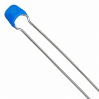
CAP CER 15000PF 50V X7R RADIAL
Manufacturer
Murata Electronics North America
Series
RPEr
Datasheets
1.RPEF51H104Z2K1A03B.pdf
(2 pages)
2.RPEF51H104Z2K1A03B.pdf
(23 pages)
3.RPEF51H104Z2K1A03B.pdf
(3 pages)
4.RPER71H153K2P1A03B.pdf
(1 pages)
Specifications of RPER71H153K2P1A03B
Capacitance
0.015µF
Voltage - Rated
50V
Tolerance
±10%
Temperature Coefficient
X7R
Mounting Type
Through Hole
Operating Temperature
-55°C ~ 125°C
Applications
General Purpose
Package / Case
Radial
Size / Dimension
0.138" L x 0.197" W (3.50mm x 5.00mm)
Thickness
2.50mm Max
Lead Spacing
0.098" (2.50mm)
Lead Style
Kinked
Lead Free Status / RoHS Status
Lead free / RoHS Compliant
Features
-
Ratings
-
Other names
490-3818


1
!Note
!Note
16
No.
10
11
12 Solderability of Leads
13
14
Specifications and Test Methods
Continued from the preceding page.
Terminal
Strength
Vibration
Resistance
Resistance
to
Soldering
Heat
Temperature
and
Immersion
Cycle
• Please read rating and !CAUTION (for storage and operating, rating, soldering and mounting, handling) in this catalog to prevent smoking and/or burning, etc.
• This catalog has only typical specifications because there is no space for detailed specifications. Therefore, please approve our product specification or transact the approval sheet for product specification before ordering.
Please read rating and !CAUTION (for storage and operating, rating, soldering and mounting, handling) in this PDF catalog to prevent smoking and/or burning, etc.
This catalog has only typical specifications. Therefore, you are requested to approve our product specification or to transact the approval sheet for product specificaion before ordering.
Item
Tensile
Strength
Bending
Strength
Appearance
Capacitance
Q/D.F.
Appearance No defects or abnormalities.
Capacitance
Change
Dielectric
Strength
(Between
Terminals)
Appearance No defects or abnormalities.
Capacitance
Change
Q/D.F.
Insulation
Resistance
Dielectric
Strength
(Between
Terminals)
Temperature Compensating Type High Dielectric Constant Type
Termination not to be broken or loosened.
Termination not to be broken or loosened.
No defects or abnormalities.
Within the specified tolerance.
30pF min. : Q U 1000
30pF max. : Q U 400+20C
C : Nominal capacitance (pF)
Solder is deposited on unintermittently immersed portion in axial
direction covering 3/4 or more in circumferential direction of lead
wires.
Within T2.5% or T0.25pF
(Whichever is larger)
No defects.
Within T5% or T0.5pF
(Whichever is larger)
30pF min. : Q U 350
10pF to 30pF : Q U 275W
10pF max. : Q U 200W10C
C : Nominal capacitance (pF)
10000MΩ or 500Ω • F min.
(Whichever is smaller)
No defects or abnormalities.
Specification
5
2
C
X7R
Z5U
Y5V : 0.05 max.
X7R : Within T7.5%
Z5U
Y5V
X7R : Within T12.5%
Z5U
Y5V
X7R : 0.05 max.
Z5U
Y5V
X7R : 10000MΩ or 500Ω • F min.
Z5U
Y5V
}
}
}
}
}
: 0.025 max.
: Within T20%
: Within T30%
: 0.075 max.
:
1000MΩ or 50Ω • F min.
(Whichever is smaller)
(Whichever is smaller)
As in the figure, fix the capacitor body, apply the force
gradually to each lead in the radial direction of the
capacitor until reaching 10N* and then keep applied
the force for 10T1 seconds.
Each lead wire shall be subjected to a force of 2.5N
and then be bent 90˚ at the point of egress in one
direction. Each wire is then returened to the original
position and bent 90˚ in the opposite direction at the
rate of one bend per 2-3 seconds.
The capacitor is soldered securely to a supporting
terminal and a 10 to 55Hz vibration of 1.5mm peak-
peak amplitude is applied for six hours total, 2 hours in
each mutually perpendicular direction. Allow 1 minute
to cycle the frequency from 10Hz to 55Hz and the
converse.
The terminal of a capacitor is dipped into a 25 %
ethanol (JIS-K-8101) solution of rosin (JIS-K-5902) and
then into molten solder (JIS-H-4341, H63A) of 235T5˚C
for 2 seconds T0.5 seconds. In both cases the depth of
dipping is up to about 1.5mm to 2mm from the terminal
body.
The lead wire is immersed in the melted solder (JIS-H-
4341, H63A) 1.5mm to 2mm from the main body at
270T5˚C for 3T0.5 seconds (L3.5gW3.0 (mm) type) or
350T10˚C for 3.5 seconds T0.5 seconds (all other
types). The specified items are measured after 24
hours T2 hours (temperature compensating type) or 48
hours T4 hours (high dielectric type).
• Initial measurement for high dielectric constant type.
The capacitors are heat treated for one hour at 150
˚C, allowed to set at room temperature for 48 hours T4
hours, and given an initial measurement.
First, repeat the following temperature/time cycle five
times :
lowest operating temperature T3˚C/30T3 minutes
Next, repeat twice the sucessive cycles of immersion,
each cycle consisting of immersion in a fresh water at
65
aqueous solution of salt at 0T3˚C for 15 minutes.
The capacitor is then promptly washed in running
water, dried with a drying cloth, and allowed to sit at
room temperature for 24 hours T2 hours (temperature
compensating type) or 48 hours T4 hours (high
dielectric type).
• Initial measurement for high dielectric constant type.
The capacitors are heat treated for one hour at
150
hours T4 hours, and given an initial measurement.
W5
Y0
ordinary temperature/3 minutes max.
highest operating temperature T3˚C/30T3 minutes
ordinary temperature/3 minutes max.
W 0
Y10
˚C for 15 minutes and immersion in a saturated
˚C, allowed to sit at room temperature for 48
F
Test Method
Continued on the following page.
* 5N for L3.5gW3.0 (mm)
C49E14.pdf 02.9.17
W 0
Y10
Related parts for RPER71H153K2P1A03B
Image
Part Number
Description
Manufacturer
Datasheet
Request
R

Part Number:
Description:
BUZZER PIEZO 25VP-P SMD
Manufacturer:
Murata Electronics North America

Part Number:
Description:
CAP 4-ARRAY 680PF 100V X7R 1206
Manufacturer:
Murata Electronics North America
Datasheet:
Part Number:
Description:
CAP 4-ARRAY 1000PF 100V X7R 1206
Manufacturer:
Murata Electronics North America
Datasheet:
Part Number:
Description:
CAP 4-ARRAY 1800PF 100V X7R 1206
Manufacturer:
Murata Electronics North America
Datasheet:
Part Number:
Description:
CAP 4-ARRAY 68000PF 16V X7R 1206
Manufacturer:
Murata Electronics North America
Datasheet:

Part Number:
Description:
CAP CER 1000PF 50V 10% X7R 0402
Manufacturer:
Murata Electronics North America
Datasheet:
Part Number:
Description:
CAP CER 10000PF 16V 10% X7R 0402
Manufacturer:
Murata Electronics North America
Datasheet:

Part Number:
Description:
CAP 5.5-25PF 2.5X3.2MM SMD
Manufacturer:
Murata Electronics North America
Datasheet:

Part Number:
Description:
CAP 4.5-20PF 2.5X3.2MM SMD
Manufacturer:
Murata Electronics North America
Datasheet:

Part Number:
Description:
CAP 5.0-20PF 3.2X4.5MM SMD RED
Manufacturer:
Murata Electronics North America
Datasheet:

Part Number:
Description:
CAP 2.0-6.0PF 3.2X4.5MM SMD BLU
Manufacturer:
Murata Electronics North America
Datasheet:

Part Number:
Description:
CAP 1.4-3.0PF 3.2X4.5MM SMD BRN
Manufacturer:
Murata Electronics North America
Datasheet:

Part Number:
Description:
CAP 3.0-10PF 3.2X4.5MM SMD WHT
Manufacturer:
Murata Electronics North America
Datasheet:

Part Number:
Description:
CAP 2.0-6.0PF 4X4.5MM TOPADJ BLU
Manufacturer:
Murata Electronics North America
Datasheet:

Part Number:
Description:
CAP 8.5-40PF 4X4.5MM TOPADJ YEL
Manufacturer:
Murata Electronics North America
Datasheet: