CKG57KX7R2E474M TDK Corporation, CKG57KX7R2E474M Datasheet - Page 9
CKG57KX7R2E474M
Manufacturer Part Number
CKG57KX7R2E474M
Description
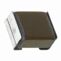
CAP CER .47UF 250V X7R STCKD SMD
Manufacturer
TDK Corporation
Series
CKGr
Datasheet
1.CKG32KX7R1E475M.pdf
(15 pages)
Specifications of CKG57KX7R2E474M
Capacitance
0.47µF
Voltage - Rated
250V
Tolerance
±20%
Temperature Coefficient
X7R
Mounting Type
Surface Mount, MLCC
Operating Temperature
-55°C ~ 125°C
Features
Stacked
Applications
Automotive
Package / Case
Non-Standard SMD
Size / Dimension
0.256" L x 0.217" W (6.50mm x 5.50mm)
Thickness
3.50mm Max
Voltage Rating
25 Volts
Operating Temperature Range
- 55 C to + 125 C
Temperature Coefficient / Code
X7R
Product
Low ESR MLCCs
Dimensions
5.5 mm W x 6.5 mm L x 3.5 mm H
Termination Style
SMD/SMT
Lead Free Status / RoHS Status
Lead free / RoHS Compliant
Ratings
-
Lead Spacing
-
Lead Free Status / Rohs Status
Details
Other names
445-4107-2


• All specifications are subject to change without notice. Please read the precautions before using the product.
No.
1
2
3
4
5
6
7
General
Specifications
Item
External
Appearance
Insulation
Resistance
Voltage Proof
Capacitance
Dissipation
Factor
(Class 2)
Temperature
Characteristics
of Capacitance
Robustness of
Terminations
Performance
No defects which may affect
performance.
500MΩ•μF min.
(As for the capacitors of rated voltage
16V DC, 100MΩ•μF min.), whichever
smaller.
Withstand test voltage without
insulation breakdown or other damage.
Within the specified tolerance.
Capacitance Change (%)
No sign of termination coming off,
breakage of ceramic, or other abnormal
signs.
T.C.
X5R
X7R
X7S
X7T
No Voltage Applied
D.F.
0.045 max.
0.045 max.
0.075 max.
0.010 max.
CKG Series — Mega Cap Type Capacitors
X5R: ± 15%
X7R: ± 15%
X7S:
X7T:
+ 22/-33%
± 22%
Test or Inspection Method
Inspect with magnifying glass (3×).
Apply rated voltage for 60s.
As for the rated voltage 630V DC, apply 500V DC.
Above DC voltage shall be applied for 1 to 5s.
Charge / discharge current shall not exceed 50mA.
See No.4 in this table for measuring condition.
Capacitance shall be measured by the steps shown in
the following table after thermal equilibrium is obtained
for each step.
∆C be calculated ref. STEP3 reading
Reflow solder the capacitors on P.C. board (shown in
Appendix 1) and apply a pushing force of 5N with
10±1s.
100V and under
10uF and under
Rated Voltage
Step
Capacitance
1
2
3
4
Over 100V
Over 10uF
US Catalog // CKG Series — Mega Cap Type // Version A11
Rated
Temperature (ºC)
Reference temp. ± 2
Min. operating temp. ± 2
Reference temp. ± 2
Max. operating temp. ± 2
Capacitor
120Hz±20%
2.5 ×rated voltage
1.5 ×rated voltage
Frequency
Measuring
1kHz±10%
Apply voltage
Pushing force
P.C. board
0.5±0.2 V
1.0±0.2V
Measuring
voltage
rms
rms
Related parts for CKG57KX7R2E474M
Image
Part Number
Description
Manufacturer
Datasheet
Request
R

Part Number:
Description:
TDK DC to DC Converters, DC to AC Inverters
Manufacturer:
TDK Corporation
Datasheet:
Part Number:
Description:
TDK DC to DC Converters, DC to AC Inverters
Manufacturer:
TDK Corporation
Datasheet: