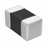
TMK063CG470JT-F Taiyo Yuden, TMK063CG470JT-F Datasheet - Page 28

TMK063CG470JT-F
Manufacturer Part Number
TMK063CG470JT-F
Description
CAP CER 47PF 25V C0G 0201
Manufacturer
Taiyo Yuden
Series
TMKr
Datasheet
1.TMK063CG220JT-F.pdf
(61 pages)
Specifications of TMK063CG470JT-F
Capacitance
47pF
Voltage - Rated
25V
Tolerance
±5%
Temperature Coefficient
C0G, NP0
Mounting Type
Surface Mount, MLCC
Operating Temperature
-55°C ~ 125°C
Applications
General Purpose
Package / Case
0201 (0603 Metric)
Size / Dimension
0.024" L x 0.012" W (0.60mm x 0.30mm)
Thickness
0.30mm
Lead Free Status / RoHS Status
Lead free / RoHS Compliant
Features
-
Ratings
-
Lead Spacing
-
Super Low Distortion Multilayer Ceramic Capacitors (CFCAP)
△
1.Operating Temperature Range
2.Storage Temperature Range
3.Rated Voltage
4.Withstanding Voltage
5.Insulation Resistance
6.Capacitance (Tolerance)
7.Tangent of Loss Angle
8.Resistance to Flexure of
9. Body strength
10. Adhesion of electrode
11. Solderability
12. Resistance to soldering
13. Thermal shock
14. Damp heat (steady state)
(tan δ)
!
RELIABILITY DATA
Between terminals
Substrate
当社カタログをご使用の際には 「当社製品に関するお断り」 を必ずお読みください。
Item
−55 to +125℃
−55 to +125℃
10VDC, 16VDC, 25VDC, 35VDC, 50VDC,
No breakdown or damage
10000 MΩ or 500MΩμF, whichever is smaller
±10%
0.1%max
Appearance: No abnormality
Capacitance change: ±5%
No separation or indication of separation of electrode.
At least 95% of terminal electrode is covered by new solder.
Apppearance: No abnormality
Capacitance change: ±2.5% max.
tanδ: Initial value
Insulation resistance: Initial value
Withstanding voltage (between terminals) : No abnormality
Appearance: No abnormality
Capacitance change: ±2.5% max
tanδ: Initial value
Insulation resistance: Initial value
Withstanding voltage (between terminals) : No abnormality
Appearance: No abnormality
Capacitance change: ±5% max
tanδ: 0.5% max
Insulation resistance 50MΩμF or 1000MΩ whichever is smaller
Specified Value
9
△
!
Please read the "Notice for TAIYO YUDEN products" before using this catalog.
Applied voltage: Rated voltage×3
Duration: 1 to 5 sec.
Charge/discharge current: 50mA max.
Applied voltage: Rated voltage
Duration: 60±5 sec.
Charge/discharge current: 50mA max.
Measuring frequency:1kHz±10%
Measuring voltage:1±0.2Vrms
Bias application: None
Measuring frequency:1kHz±10%
Measuring voltage:1±0.2Vrms
Bias application: None
Warp: 1mm
Speed: 0.5mm/second
Duration:10 seconds
The measurement shall be made with the board in the bent position.
Applied force: 5N
Duration: 30 ±5 seconds
Solder temp.: 230 ±5℃
Duration: 4 ±1 seconds
Solder temp.: 270 ±5℃
Duration: 3 ±0.5 seconds
Preheating conditions: 80 to 100℃, 2 to 5 min. or 5 to 10 min.
Recovery: Recovery for the following period under the
standard condition after the test: 24 ±2hrs
Conditions for 1 cycle:
Step 1: Minimum operating temperature
Step 2: Room temperature
Step 3: Maximum operating temperature
Step 4: Room temperature
Number of cycles: 5 times
Recovery after the test: 24±2hrs
Temperature:40±2℃
Humidity:90 to 95% RH
Duration:500
Recovery: Recovery for the following period under the stan-
dard condition after the removal from test chamber: 24 ±2hrs
R-230
+24
−
Test Methods and Remarks
0
hrs
150 to 200℃, 2 to 5 min. or 5 to 10 min.
−
+0
−
+3
3
0
℃ 30±3 minutes
℃ 30±3 minutes
2 to 3min.
2 to 3min.
1/2
73
4


