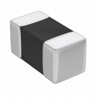
TMK063CG470JT-F Taiyo Yuden, TMK063CG470JT-F Datasheet - Page 54

TMK063CG470JT-F
Manufacturer Part Number
TMK063CG470JT-F
Description
CAP CER 47PF 25V C0G 0201
Manufacturer
Taiyo Yuden
Series
TMKr
Datasheet
1.TMK063CG220JT-F.pdf
(61 pages)
Specifications of TMK063CG470JT-F
Capacitance
47pF
Voltage - Rated
25V
Tolerance
±5%
Temperature Coefficient
C0G, NP0
Mounting Type
Surface Mount, MLCC
Operating Temperature
-55°C ~ 125°C
Applications
General Purpose
Package / Case
0201 (0603 Metric)
Size / Dimension
0.024" L x 0.012" W (0.60mm x 0.30mm)
Thickness
0.30mm
Lead Free Status / RoHS Status
Lead free / RoHS Compliant
Features
-
Ratings
-
Lead Spacing
-
Multilayer Ceramic Capacitor Chips
△
10.Body Strength
11.Adhesion of Electrode
12.Solderability
13.Resistance to soldering
14.Thermal shock
15.Damp Heat (steady state)
!
RELIABILITY DATA
当社カタログをご使用の際には 「当社製品に関するお断り」 を必ずお読みください。
Item
(between terminals) :
(between terminals) :
No separation or indication of separation of electrode.
At least 95% of terminal electrode is covered by new solder.
Appearance: No ab-
normality
Capacitance change:
W i t h i n ± 2 . 5 % o r
±0.25pF, whichever is
larger.
Q: Initial value
Insulation resistance:
Initial value
Withstanding voltage
No abnormality
Appearance: No ab-
normality
Capacitance change:
W i t h i n ± 2 . 5 % o r
±0.25pF, whichever is
larger.
Insulation resistance:
Initial value
Withstanding voltage
No abnormality
Appearance: No ab-
normality
Capacitance change:
Within ±5% or ±0.5pF,
whichever is larger.
Q:
C≧30 pF
10 ≦ C < 30 p F : Q ≧
275 + 2.5C
C<10 pF
+ 10C
C: Nominal capacitance
Insulation resistance:
1000 MΩ min.
Q: Initial value
Temperature Compensating (Class 1)
Standard
: Q≧350
: Q≧200
(between terminals) :
(between terminals) :
No mechanical dam-
age.
Appearance: No ab-
normality
Capacitance change:
Within ±2.5%
Q: Initial value
Insulation resistance:
Initial value
Withstanding voltage
No abnormality
Appearance: No ab-
normality
Capacitance change:
Within ±0.25pF
Q: Initial value
Insulation resistance:
Initial value
Withstanding voltage
No abnormality
Appearance: No ab-
normality
Capacitance change:
Within ±0.5pF,
Insulation resistance:
1000 MΩ min.
High Frequency Type
Specified Value
Appearance: No abnormality
Capacitance change: Within ±7.5% (BJ)
tan δ: Initial value
Insulation resistance: Initial value
Withstanding voltage (between terminals) : No
abnormality
Appearance: No abnormality
Capacitance change: Within ±7.5% (BJ)
tan δ: Initial value
Insulation resistance: Initial value
Withstanding voltage (between terminals) : No
abnormality
Appearance: No ab-
normality
Capacitance change:
tan δ: BJ: 5.0% max.
Note 4
Insulation resistance:
50 MΩμF or 1000 MΩ
whichever is smaller.
Note 5
BJ: Within ±12.5%
F: Within ±30%
Standard Note1
F: 7.5% max.
High Permittivity (Class 2)
Within ±20% (F)
Within ±20% (F)
Appearance: No ab-
normality
Capacitance change:
BJ:Within ±12.5%
Note 4
tan δ:
BJ: 5.0% max. Note 4.
F: 11.0% max.
Insulation resistance:
50 MΩμF or 1000 MΩ
whichever is smaller.
Note 5
High Value
Note 4
Note 4
△
!
Please read the "Notice for TAIYO YUDEN products" before using this catalog.
High Frequency Multilayer:
Applied force: 5N
Applied force: 5N
Duration: 30±5 sec.
Solder temperature: 230±5℃
Preconditioning: Thermal treatment (at 150℃ for 1 hr)
Solder temperature: 270±5℃
Duration: 3±0.5 sec.
Preheating conditions: 80 to 100℃, 2 to 5 min. or 5 to 10 min.
Recovery: Recovery for the following period under the
standard condition after the test.
Preconditioning: Thermal treatment (at 150℃ for 1 hr)
Conditions for 1 cycle:
Step 1: Minimum operating temperature
Step 2: Room temperature
Step 3: Maximum operating temperature
Step 4: Room temperature
Number of cycles: 5 times
Recovery after the test: 6∼24 hrs (Class 1)
Multilayer:
Preconditioning: Thermal treatment (at 150℃ for 1 hr)
Temperature: 40±2℃
Humidity: 90 to 95% RH
Duration: 500
Recovery: Recovery for the following period under the
standard condition after the removal from test chamber.
HighーFrequency Multilayer:
Temperature: 60±2℃
Humidity: 90 to 95% RH
Duration: 500
Recovery: Recovery for the following period under the
standard condition after the removal from test chamber.
Duration: 10 sec.
Duration: 4±1 sec.
6∼24 hrs (Class 1)
24±2 hrs (Class 2)
(LW Reverse)
6∼24 hrs (Class 1)
24±2 hrs (Class 2)
6∼24 hrs (Class 1)
+24
−
+24
−
Test Methods and Remarks
(Applicable to Class 2.)
(Applicable to Class 2.)
0
0
(Applicable to Class 2.)
A
hrs
hrs
150 to 200℃, 2 to 5 min. or 5 to 10 min.
(01005, 0201, 0302 TYPE 2N)
24±2 hrs (Class 2)
A
+
−
A
−
+
0
3
0
3
℃ 30±3 min.
℃ 30±3 min.
2 to 3 min.
2 to 3 min.
2/3
105
4


