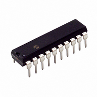
PIC16F677-I/P Microchip Technology, PIC16F677-I/P Datasheet - Page 10

PIC16F677-I/P
Manufacturer Part Number
PIC16F677-I/P
Description
IC PIC MCU FLASH 2KX14 20DIP
Manufacturer
Microchip Technology
Series
PIC® 16Fr
Datasheets
1.PIC16F616T-ISL.pdf
(8 pages)
2.PIC16F690DM-PCTLHS.pdf
(306 pages)
3.PIC16F677-IP.pdf
(2 pages)
4.PIC16F677-IP.pdf
(16 pages)
5.PIC16F677-ISO.pdf
(294 pages)
Specifications of PIC16F677-I/P
Program Memory Type
FLASH
Program Memory Size
3.5KB (2K x 14)
Package / Case
20-DIP (0.300", 7.62mm)
Mfg Application Notes
Intro to Capacitive Sensing Appl Notes Layout and Physical Design Appl Note
Core Processor
PIC
Core Size
8-Bit
Speed
20MHz
Connectivity
I²C, SPI
Peripherals
Brown-out Detect/Reset, POR, WDT
Number Of I /o
18
Eeprom Size
256 x 8
Ram Size
128 x 8
Voltage - Supply (vcc/vdd)
2 V ~ 5.5 V
Data Converters
A/D 12x10b
Oscillator Type
Internal
Operating Temperature
-40°C ~ 85°C
Processor Series
PIC16F
Core
PIC
Data Bus Width
8 bit
Data Ram Size
128 B
Interface Type
SSP
Maximum Clock Frequency
20 MHz
Number Of Programmable I/os
17
Number Of Timers
2
Operating Supply Voltage
2 V to 5.5 V
Maximum Operating Temperature
+ 85 C
Mounting Style
Through Hole
3rd Party Development Tools
52715-96, 52716-328, 52717-734
Development Tools By Supplier
PG164130, DV164035, DV244005, DV164005, PG164120, ICE2000, DM163014, DM164120-4
Minimum Operating Temperature
- 40 C
On-chip Adc
12-ch x 10-bit
Lead Free Status / RoHS Status
Lead free / RoHS Compliant
For Use With
AC162061 - HEADER INTRFC MPLAB ICD2 20PINACICE0203 - MPLABICE 20P 300 MIL ADAPTER
Lead Free Status / Rohs Status
Lead free / RoHS Compliant
Available stocks
Company
Part Number
Manufacturer
Quantity
Price
Company:
Part Number:
PIC16F677-I/P
Manufacturer:
MICROCHIP
Quantity:
2 000
PIC16F631/677/685/687/689/690
Table of Contents
1.0
2.0
3.0
4.0
5.0
6.0
7.0
8.0
9.0
10.0 Data EEPROM and Flash Program Memory Control ............................................................................................................... 119
11.0 Enhanced Capture/Compare/PWM Module ............................................................................................................................. 127
12.0 Enhanced Universal Synchronous Asynchronous Receiver Transmitter (EUSART) ............................................................... 149
13.0 SSP Module Overview ............................................................................................................................................................. 175
14.0 Special Features of the CPU .................................................................................................................................................... 193
15.0 Instruction Set Summary .......................................................................................................................................................... 213
16.0 Development Support............................................................................................................................................................... 223
17.0 Electrical Specifications............................................................................................................................................................ 227
18.0 DC and AC Characteristics Graphs and Tables ....................................................................................................................... 255
19.0 Packaging Information.............................................................................................................................................................. 275
Appendix A: Data Sheet Revision History.......................................................................................................................................... 281
Appendix B: Migrating from other PICmicro® Devices ...................................................................................................................... 281
DS41262C-page 8
It is our intention to provide our valued customers with the best documentation possible to ensure successful use of your Microchip
products. To this end, we will continue to improve our publications to better suit your needs. Our publications will be refined and
enhanced as new volumes and updates are introduced.
If you have any questions or comments regarding this publication, please contact the Marketing Communications Department via E-
mail at docerrors@microchip.com or fax the Reader Response Form in the back of this data sheet to (480) 792-4150. We wel-
come your feedback.
Most Current Data Sheet
To obtain the most up-to-date version of this data sheet, please register at our Worldwide Web site at:
You can determine the version of a data sheet by examining its literature number found on the bottom outside corner of any page.
The last character of the literature number is the version number, (e.g., DS30000A is version A of document DS30000).
Errata
An errata sheet, describing minor operational differences from the data sheet and recommended workarounds, may exist for current
devices. As device/documentation issues become known to us, we will publish an errata sheet. The errata will specify the revision of
silicon and revision of document to which it applies.
To determine if an errata sheet exists for a particular device, please check with one of the following:
• Microchip’s Worldwide Web site; http://www.microchip.com
• Your local Microchip sales office (see last page)
When contacting a sales office, please specify which device, revision of silicon and data sheet (include literature number) you are
using.
Customer Notification System
Register on our web site at www.microchip.com to receive the most current information on all of our products.
http://www.microchip.com
Device Overview .......................................................................................................................................................................... 9
Memory Organization ................................................................................................................................................................. 25
Oscillator Module (With Fail-Safe Clock Monitor)....................................................................................................................... 47
I/O Ports ..................................................................................................................................................................................... 59
Timer0 Module ........................................................................................................................................................................... 81
Timer1 Module with Gate Control............................................................................................................................................... 84
Timer2 Module ........................................................................................................................................................................... 91
Comparator Module.................................................................................................................................................................... 93
Analog-to-Digital Converter (ADC) Module .............................................................................................................................. 107
TO OUR VALUED CUSTOMERS
Preliminary
© 2006 Microchip Technology Inc.


