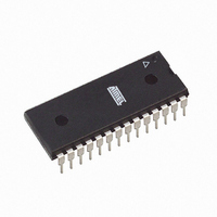
ATMEGA168-20PU Atmel, ATMEGA168-20PU Datasheet - Page 355

ATMEGA168-20PU
Manufacturer Part Number
ATMEGA168-20PU
Description
IC AVR MCU 16K 20MHZ 28DIP
Manufacturer
Atmel
Series
AVR® ATmegar
Datasheets
1.ATAVRTS2080B.pdf
(378 pages)
2.ATMEGA48-20AU.pdf
(35 pages)
3.ATMEGA88-20MU.pdf
(33 pages)
4.ATMEGA168-20AU.pdf
(359 pages)
Specifications of ATMEGA168-20PU
Core Processor
AVR
Core Size
8-Bit
Speed
20MHz
Connectivity
I²C, SPI, UART/USART
Peripherals
Brown-out Detect/Reset, POR, PWM, WDT
Number Of I /o
23
Program Memory Size
16KB (8K x 16)
Program Memory Type
FLASH
Eeprom Size
512 x 8
Ram Size
1K x 8
Voltage - Supply (vcc/vdd)
2.7 V ~ 5.5 V
Data Converters
A/D 6x10b
Oscillator Type
Internal
Operating Temperature
-40°C ~ 85°C
Package / Case
28-DIP (0.300", 7.62mm)
Processor Series
ATMEGA16x
Core
AVR8
Data Bus Width
8 bit
Data Ram Size
1 KB
Interface Type
2-Wire, SPI, USART, Serial
Maximum Clock Frequency
20 MHz
Number Of Programmable I/os
23
Number Of Timers
3
Operating Supply Voltage
2.7 V to 5.5 V
Maximum Operating Temperature
+ 85 C
Mounting Style
Through Hole
3rd Party Development Tools
EWAVR, EWAVR-BL
Development Tools By Supplier
ATAVRDRAGON, ATSTK500, ATSTK600, ATAVRISP2, ATAVRONEKIT
Minimum Operating Temperature
- 40 C
On-chip Adc
10 bit, 6 Channel
A/d Inputs
6-Channel, 10-Bit
Cpu Speed
20 MIPS
Eeprom Memory
512 Bytes
Input Output
23
Interface
I2C/SPI/UART/USART
Memory Type
Flash
Number Of Bits
8
Package Type
28-pin PDIP
Programmable Memory
16K Bytes
Timers
2-8-bit, 1-16-bit
Voltage, Range
4.5-5.5 V
Controller Family/series
AVR MEGA
No. Of I/o's
23
Eeprom Memory Size
512Byte
Ram Memory Size
1KB
Rohs Compliant
Yes
For Use With
ATSTK600-TQFP32 - STK600 SOCKET/ADAPTER 32-TQFPATSTK600 - DEV KIT FOR AVR/AVR32770-1007 - ISP 4PORT ATMEL AVR MCU SPI/JTAGATAVRDRAGON - KIT DRAGON 32KB FLASH MEM AVRATAVRISP2 - PROGRAMMER AVR IN SYSTEMATJTAGICE2 - AVR ON-CHIP D-BUG SYSTEM
Lead Free Status / RoHS Status
Lead free / RoHS Compliant
Available stocks
Company
Part Number
Manufacturer
Quantity
Price
Part Number:
ATMEGA168-20PU
Manufacturer:
ATMEL/爱特梅尔
Quantity:
20 000
- ATAVRTS2080B PDF datasheet
- ATMEGA48-20AU PDF datasheet #2
- ATMEGA88-20MU PDF datasheet #3
- ATMEGA168-20AU PDF datasheet #4
- Current page: 355 of 359
- Download datasheet (3Mb)
2545E–AVR–02/05
14 Timer/Counter0 and Timer/Counter1 Prescalers .............................. 135
15 8-bit Timer/Counter2 with PWM and Asynchronous Operation ...... 138
16 Serial Peripheral Interface – SPI ......................................................... 159
17 USART0 ................................................................................................. 168
13.1Overview .............................................................................................................106
13.2Accessing 16-bit Registers ..................................................................................108
13.3Timer/Counter Clock Sources .............................................................................111
13.4Counter Unit ........................................................................................................112
13.5Input Capture Unit ...............................................................................................113
13.6Output Compare Units .........................................................................................115
13.7Compare Match Output Unit ................................................................................117
13.8Modes of Operation .............................................................................................118
13.9Timer/Counter Timing Diagrams .........................................................................125
13.1016-bit Timer/Counter Register Description ........................................................128
15.1Overview .............................................................................................................138
15.2Timer/Counter Clock Sources .............................................................................139
15.3Counter Unit ........................................................................................................139
15.4Output Compare Unit ..........................................................................................140
15.5Compare Match Output Unit ................................................................................142
15.6Modes of Operation .............................................................................................143
15.7Timer/Counter Timing Diagrams .........................................................................147
15.88-bit Timer/Counter Register Description ............................................................149
15.9Asynchronous operation of the Timer/Counter ....................................................155
15.10Timer/Counter Prescaler ...................................................................................158
16.1SS Pin Functionality ............................................................................................164
16.2Data Modes .........................................................................................................166
17.1Overview .............................................................................................................168
17.2Clock Generation .................................................................................................169
17.3Frame Formats ....................................................................................................172
17.4USART Initialization ............................................................................................174
17.5Data Transmission – The USART Transmitter ....................................................176
17.6Data Reception – The USART Receiver .............................................................178
17.7Asynchronous Data Reception ............................................................................182
17.8Multi-processor Communication Mode ................................................................185
17.9USART Register Description ...............................................................................187
iii
Related parts for ATMEGA168-20PU
Image
Part Number
Description
Manufacturer
Datasheet
Request
R

Part Number:
Description:
Manufacturer:
Atmel Corporation
Datasheet:

Part Number:
Description:
Manufacturer:
Atmel Corporation
Datasheet:

Part Number:
Description:
Manufacturer:
ATMEL Corporation
Datasheet:

Part Number:
Description:
IC AVR MCU 16K 20MHZ 32TQFP
Manufacturer:
Atmel
Datasheet:

Part Number:
Description:
IC AVR MCU 16K 20MHZ 32-QFN
Manufacturer:
Atmel
Datasheet:

Part Number:
Description:
MCU AVR 16K FLASH 15MHZ 32-TQFP
Manufacturer:
Atmel
Datasheet:

Part Number:
Description:
MCU AVR 16K FLASH 15MHZ 32-QFN
Manufacturer:
Atmel
Datasheet:

Part Number:
Description:
IC AVR MCU 16K 20MHZ 32TQFP
Manufacturer:
Atmel
Datasheet:

Part Number:
Description:
MCU AVR 16KB FLASH 20MHZ 32QFN
Manufacturer:
Atmel
Datasheet:

Part Number:
Description:
MCU AVR 16KB FLASH 20MHZ 32TQFP
Manufacturer:
Atmel
Datasheet:

Part Number:
Description:
IC MCU AVR 16K FLASH 32-QFN
Manufacturer:
Atmel
Datasheet:


