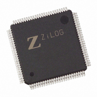
EZ80F93AZ020SG Zilog, EZ80F93AZ020SG Datasheet - Page 2

EZ80F93AZ020SG
Manufacturer Part Number
EZ80F93AZ020SG
Description
IC ACCLAIM MCU 64KB 100LQFP
Manufacturer
Zilog
Series
eZ80® Acclaim!®r
Specifications of EZ80F93AZ020SG
Core Processor
Z8
Core Size
8-Bit
Speed
20MHz
Connectivity
I²C, IrDA, SPI, UART/USART
Peripherals
Brown-out Detect/Reset, POR, WDT
Number Of I /o
24
Program Memory Size
64KB (64K x 8)
Program Memory Type
FLASH
Ram Size
4K x 8
Voltage - Supply (vcc/vdd)
3 V ~ 3.6 V
Oscillator Type
Internal
Operating Temperature
0°C ~ 70°C
Package / Case
100-LQFP
Processor Series
EZ80F93x
Core
eZ80
Data Bus Width
8 bit
Data Ram Size
4 KB
Interface Type
I2C, IrDA, SPI, UART
Maximum Clock Frequency
20 MHz
Number Of Programmable I/os
24
Number Of Timers
6
Operating Supply Voltage
3 V to 3.6 V
Maximum Operating Temperature
+ 70 C
Mounting Style
SMD/SMT
Development Tools By Supplier
eZ80F920200ZCOG
Minimum Operating Temperature
0 C
Lead Free Status / RoHS Status
Lead free / RoHS Compliant
Eeprom Size
-
Data Converters
-
Lead Free Status / Rohs Status
Details
Other names
269-3874
EZ80F93AZ020SG
EZ80F93AZ020SG
Available stocks
Company
Part Number
Manufacturer
Quantity
Price
Table 1. Errata to eZ80F92 and eZ80F93 Devices (Continued)
UP004909-0910
No
4
5
Issue
A pulse on the SCL line
when the I
and the SDA line is held
High causes the I
lock.
RTC count errors of
seconds, minutes, and
hours can occur during
eZ80F92 and eZ80F93
power-up.
2
C bus is idle
2
C to
Detailed Description
A pulse on the SCL line prior to a START condition or after a STOP
condition causes the I
the I
occurs, an I
Workarounds
1. To prevent a lock from occurring: it is possible to completely disable
2. If a lock occurs after the SCL line is released, another device on the
The eZ80F92 and eZ80F93 MCUs each contain a private test mode
register powered by V
production test) and is synchronously reset by the system clock. The
test register is not tied down during reset. If this register powers up in a
state that enables test mode, the RTC counters will start incrementing in
fast mode until the register is reset by the first toggles of the system
clock.
Workaround
During eZ80F92 and eZ80F93 power-up, gate off the RTC clock source
and hold external RESET active (at least for three system clock periods)
after V
the I
Power-Down Register 1 (CLK_PPD1). Disable the I
setting ENAB in the I
I
should unlock. Another option is to initiate an overall SYSTEM
RESET of the eZ80F91 device to reset the I
2
C bus can issue a Stop by pulsing the SDA line. As a result, the I
2
C control register ENAB settings (I2C_CTL). If this situation
DD
Product Update: Errata for eZ80F92 and eZ80F93 MCUs
2
C block prior to any bus activity using the Clock Peripheral
ramps up to 3.3 V and the system clock source is stable.
2
C software reset does not unlock the I
2
DD
C bus to lock. This situation occurs regardless of
2
. The test mode enables fast RTC counting (for
C Control register.
2
C block.
2
C bus.
2
C block before
Page 2 of 7
2
C


