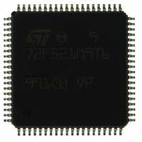
ST72F521M9T6 STMicroelectronics, ST72F521M9T6 Datasheet - Page 133

ST72F521M9T6
Manufacturer Part Number
ST72F521M9T6
Description
IC MCU 8BIT 60K FLASH 80-TQFP
Manufacturer
STMicroelectronics
Series
ST7r
Datasheet
1.ST72F521M9T6.pdf
(215 pages)
Specifications of ST72F521M9T6
Core Processor
ST7
Core Size
8-Bit
Speed
8MHz
Connectivity
CAN, LINSCI, SPI
Peripherals
LVD, POR, PWM, WDT
Number Of I /o
64
Program Memory Size
60KB (60K x 8)
Program Memory Type
FLASH
Ram Size
2K x 8
Voltage - Supply (vcc/vdd)
3.8 V ~ 5.5 V
Data Converters
A/D 16x10b
Oscillator Type
Internal
Operating Temperature
-40°C ~ 85°C
Package / Case
80-TQFP, 80-VQFP
Processor Series
ST72F5x
Core
ST7
Data Bus Width
8 bit
Data Ram Size
2048 B
Interface Type
CAN, I2C, SCI, SPI
Maximum Clock Frequency
8 MHz
Number Of Programmable I/os
64
Number Of Timers
5
Operating Supply Voltage
3.8 V to 5.5 V
Maximum Operating Temperature
+ 85 C
Mounting Style
SMD/SMT
Minimum Operating Temperature
- 40 C
On-chip Adc
10 bit
For Use With
497-6453 - BOARD EVAL BASED ON ST7LNBX497-5046 - KIT TOOL FOR ST7/UPSD/STR7 MCU
Lead Free Status / RoHS Status
Lead free / RoHS Compliant
Eeprom Size
-
Lead Free Status / Rohs Status
Details
Other names
497-8244
ST72F521M9T6
ST72F521M9T6
Available stocks
Company
Part Number
Manufacturer
Quantity
Price
Company:
Part Number:
ST72F521M9T6
Manufacturer:
ST
Quantity:
37 800
Company:
Part Number:
ST72F521M9T6
Manufacturer:
STMicroelectronics
Quantity:
10 000
Company:
Part Number:
ST72F521M9T6TR
Manufacturer:
STMicroelectronics
Quantity:
10 000
CONTROLLER AREA NETWORK (Cont’d)
– RESYNC. The resynchronization mode is used
– IDLE. The CAN controller looks for one of the fol-
– TRANSMISSION. Once the LOCK bit of a Buffer
to find the correct entry point for starting trans-
mission or reception after the node has gone
asynchronous either by going into the STANDBY
or bus-off states.
Resynchronization is achieved when 128 se-
quences of 11 recessive bits have been moni-
tored unless the node is not bus-off and the
FSYN bit in the CSR register is set in which case
a single sequence of 11 recessive bits needs to
be monitored.
lowing events: the RUN bit is reset, a Start Of
Frame appears on the CAN bus or the DATA7
register of the currently active page is written to.
Control/Status Register (BCSRx) has been set
and read back as such, a transmit job can be
submitted by writing to the DATA7 register. The
message with the highest priority will be transmit-
ted as soon as the CAN bus becomes idle.
Among those messages with a pending trans-
mission request, the highest priority is given to
Buffer 3 then 2 and 1. If the transmission fails due
to a lost arbitration or to an error while the NRTX
bit of the CSR register is reset, then a new trans-
mission attempt is performed. This goes on until
the transmission ends successfully or until the
job is cancelled by unlocking the buffer, by set-
ting the NRTX bit or if the node ever enters bus-
off or if a higher priority message becomes pend-
ing. The RDY bit in the BCSRx register, which
was set since the job was submitted, gets reset.
When a transmission is in progress, the BUSY bit
in the BCSRx register is set. If it ends successful-
ly then the TXIF bit in the Interrupt Status Regis-
ter (ISR) is set, else the TEIF bit is set. An
interrupt is generated in either case provided the
TXIE and TEIE bits of the ICR register are set.
Note 1: Setting the SRTE bit of the CSR register
allows transmitted messages to be simultane-
ously received when they pass the acceptance
filtering. This is particularly useful for checking
the integrity of the communication path.
RECEPTION. Once the CAN controller has syn-
chronized itself onto the bus activity, it is ready
for reception of new messages. Every incoming
message gets its identifier compared to the ac-
ceptance filters. If the bitwise comparison of the
selected bits ends up with a match for at least
one of the filters then that message is elected for
reception and a target buffer is searched for. This
buffer will be the first one - order is 1 to 3 - that
has the LOCK and RDY bits of its BCSRx regis-
ter reset.
– When no such buffer exists then an overrun
– When a buffer does exist, the accepted mes-
Up to three messages can be automatically
received without intervention from the CPU
because each buffer has its own set of status
bits, greatly reducing the reactiveness require-
ments in the processing of the receive inter-
rupts.
interrupt is generated if the ORIE bit of the ICR
register has been set. In this case the identifi-
er of the last message is made available in the
Last Identifier Register (LIDHR and LIDLR) at
least until it gets overwritten by a new identifi-
er picked-up from the bus.
sage gets written into it, the ACC bit in the
BCSRx register gets the number of the match-
ing filter, the RDY and RXIF bits get set and an
interrupt is generated if the RXIE bit in the ISR
register is set.
ST72F521, ST72521B
133/215


