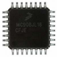
MC908JL16CFJER Freescale Semiconductor, MC908JL16CFJER Datasheet - Page 132

MC908JL16CFJER
Manufacturer Part Number
MC908JL16CFJER
Description
IC MCU 8BIT 16K FLASH 32-LQFP
Manufacturer
Freescale Semiconductor
Series
HC08r
Datasheet
1.MC908JL16CFJER.pdf
(230 pages)
Specifications of MC908JL16CFJER
Core Processor
HC08
Core Size
8-Bit
Speed
8MHz
Connectivity
I²C, SCI
Peripherals
LED, LVD, POR, PWM
Number Of I /o
26
Program Memory Size
16KB (16K x 8)
Program Memory Type
FLASH
Ram Size
512 x 8
Voltage - Supply (vcc/vdd)
2.7 V ~ 5.5 V
Data Converters
A/D 13x10b
Oscillator Type
Internal
Operating Temperature
-40°C ~ 85°C
Package / Case
32-LQFP
Controller Family/series
HC08
No. Of I/o's
26
Ram Memory Size
512Byte
Cpu Speed
8MHz
No. Of Timers
2
Digital Ic Case Style
LQFP
Rohs Compliant
Yes
Processor Series
HC08JL
Core
HC08
Data Bus Width
8 bit
Data Ram Size
512 B
Interface Type
SCI
Maximum Clock Frequency
8 MHz
Number Of Programmable I/os
26
Number Of Timers
4
Maximum Operating Temperature
+ 85 C
Mounting Style
SMD/SMT
Development Tools By Supplier
FSICEBASE, DEMO908JL16E, M68CBL05CE
Minimum Operating Temperature
- 40 C
On-chip Adc
10 bit, 13 Channel
For Use With
DEMO908JL16E - BOARD DEMO FOR MC908JL16
Lead Free Status / RoHS Status
Lead free / RoHS Compliant
Eeprom Size
-
Lead Free Status / Rohs Status
Details
Other names
MC908JL16CFJERTR
Available stocks
Company
Part Number
Manufacturer
Quantity
Price
Company:
Part Number:
MC908JL16CFJER
Manufacturer:
Freescale Semiconductor
Quantity:
29 890
Company:
Part Number:
MC908JL16CFJER
Manufacturer:
Freescale
Quantity:
198
Company:
Part Number:
MC908JL16CFJER
Manufacturer:
Freescale Semiconductor
Quantity:
10 000
Analog-to-Digital Converter (ADC)
COCO — Conversion Complete Bit
AIEN — ADC10 Interrupt Enable Bit
ADCO — ADC10 Continuous Conversion Bit
ADCH[4:0] — Channel Select Bits
132
The COCO bit is a read-only bit which is set each time a conversion is completed. This bit is cleared
whenever the status and control register is written or whenever the data register (low) is read.
When this bit is set, an interrupt is generated at the end of a conversion. The interrupt signal is cleared
when the data register is read or the status/control register is written. Reset clears the AIEN bit.
When written high, the ADC10 will begin to convert samples continuously (continuous conversion
mode) and update the result registers at the end of each conversion, provided the ADCH[4:0] bits do
not decode to all 1s. The ADC10 will continue to convert until the MCU enters reset, the MCU enters
stop mode (if ACLKEN is clear), the ADCLK register is written, or until the ADCSC is written again. If
Stop is entered (with ACLKEN low), continuous conversions will cease and can only be restarted with
a write to the ADCSC. Any write to the ADCSC with the ADCO bit set and the ADCH bits not all 1s will
abort the current conversion and begin continuous conversions.
If the bus frequency is less than the ADCK frequency, precise sample time for continuous conversions
cannot be guaranteed in short-sample mode (ADLSMP = 0). If the bus frequency is less than 1/11th
of the ADCK frequency, precise sample time for continuous conversions cannot be guaranteed in
long-sample mode (ADLSMP = 1).
When clear, the ADC10 will perform a single conversion (single conversion mode) each time the
ADCSC is written (assuming the ADCH[4:0] bits do not decode all 1s). Reset clears the ADCO bit.
ADCH4, ADCH3, ADCH2, ADCH1, and ADCH0 form a 5-bit field which is used to select one of the
input channels. The input channels are detailed in
The successive approximation converter subsystem is turned off when the channel select bits are all
set to 1. This feature allows for explicit disabling of the ADC10 and isolation of the input channel from
the I/O pad. Terminating continuous convert mode this way will prevent an additional, single
conversion from being performed. It is not necessary to set the channel select bits to all 1s to place the
ADC10 in a low-power state, however, because the module is automatically placed in a low-power
state when a conversion completes.
1 = Conversion completed
0 = Conversion not completed
1 = ADC10 interrupt enabled
0 = ADC10 interrupt disabled
1 = Continuous conversion following a write to the ADCSC
0 = One conversion following a write to the ADCSC
MC68HC908JL16 Data Sheet, Rev. 1.1
Table
9-2.
Freescale Semiconductor


