R5F21102DFP#U0 Renesas Electronics America, R5F21102DFP#U0 Datasheet - Page 85
R5F21102DFP#U0
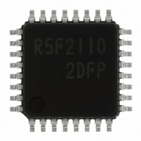
Manufacturer Part Number
R5F21102DFP#U0
Description
IC R8C MCU FLASH 8K 32LQFP
Manufacturer
Renesas Electronics America
Series
M16C™ M16C/R8C/Tiny/10r
Datasheets
1.R5F211A2SPU0.pdf
(300 pages)
2.R5F21102FPU0.pdf
(30 pages)
3.R5F21102FPU0.pdf
(201 pages)
Specifications of R5F21102DFP#U0
Core Processor
R8C
Core Size
16-Bit
Speed
16MHz
Connectivity
SIO, UART/USART
Peripherals
LED, WDT
Number Of I /o
22
Program Memory Size
8KB (8K x 8)
Program Memory Type
FLASH
Ram Size
512 x 8
Voltage - Supply (vcc/vdd)
2.7 V ~ 5.5 V
Data Converters
A/D 8x10b
Oscillator Type
Internal
Operating Temperature
-40°C ~ 85°C
Package / Case
32-LQFP
For Use With
R0K521134S000BE - KIT EVAL STARTER FOR R8C/13R0E521134EPB00 - KIT EMULATOR PROBE FOR PC7501R0E521134CPE00 - EMULATOR COMPACT R8C/13
Lead Free Status / RoHS Status
Lead free / RoHS Compliant
Eeprom Size
-
Available stocks
Company
Part Number
Manufacturer
Quantity
Price


R8C/10 Group
Rev.1.20 Jan 27, 2006
REJ09B0019-0120
Figure 12.19 TYZMR Register
Figure 12.18 Timer Z Block Diagram
12.3 Timer Z
Timer Z is an 8-bit timer with an 8-bit prescaler and has two reload registers-Timer Z Primary and Timer
Z Secondary. Figure 12.18 shows a block diagram of Timer Z. Figures 12.19 to 12.21 show the TYZMR,
PREZ, TZSC, TZPR, TYZOC, PUM, and TCSS registers.
Timer Z has the following four operation modes.
T i m e r Y u n d e r f l o w
• Timer mode: The timer counts an internal count source or Timer Y underflow.
• Programmable waveform generation mode: The timer outputs pulses of a given width successively.
• Programmable one-shot generation mode: The timer outputs one-shot pulse.
• Programmable wait one-shot generation mode: The timer outputs delayed one-shot pulse.
T Z M O D 1 t o T Z M O D 0 = 0 1
T Z
Timer Y, Z mode register
b 7 b 6 b 5 b 4 b 3 b 2 b 1 b 0
INT0
O U T
N O T E S :
T Z C K 1 t o T Z C K 0
1 . T h e I R b i t i n t h e I N T 2 I C r e g i s t e r m a y b e s e t t o “ 1 ” ( i n t e r r u p t r e q u e s t e d ) w h e n t h e R 1 E D G b i t i s r e w r i t t e n .
R e f e r t o t h e p a r a g r a p h 1 9 . 2 . 5 “ C h a n g i n g I n t e r r u p t F a c t o r ” i n t h e U s a g e N o t e s R e f e r e n c e B o o k .
f
f
f
1
8
2
= 1 0
= 1 1
=01
= 0 0
2
2
2
2
2
page 73 of 180
, 1 0
2
, 1 1
2
T Z O C N T = 1
TZOCNT=0
Digital
filter
Bit symbol
T Y M O D 0
T Y W C
T Y S
T Z M O D 0
T Z M O D 1
T Z W C
T Z S
R 1 E D G
P3_1 bit in P3 register
Input polarity selected to be
one edge or both edges
S y m b o l
T Y Z M R
INT0PL
R e l o a d r e g i s t e r
P R E Z r e g i s t e r
C o u n t e r
INT2/CNTR
switching bit
T i m e r Y o p e r a t i o n
m o d e b i t
T i m e r Y w r i t e
c o n t r o l b i t
T i m e r Y c o u n t
s t a r t f l a g
T i m e r Z o p e r a t i o n
m o d e b i t
T i m e r Z w r i t e
c o n t r o l b i t
T i m e r Z c o u n t
s t a r t f l a g
INT0EN
Bit name
T Z S
1
(1)
A d d r e s s
polarity
0 0 8 0
1 6
T Z M O D 1 t o T Z M O D 0 = 1 0
Data bus
0 : Timer mode
1 : Programmable waveform generation mode
0 : Rising edge
1 : Falling edge
Function varies depending on the operation
mode
0 : Stops counting
1 : Starts counting
b 5 b 4
0 0 : Timer mode
0 1 : Programmable waveform generation mode
1 0 : Programmable one-shot generation mode
1 1 : Programmable wait one-shot generation
Function varies depending on the operation
mode
0 : Stops counting
1 : Starts counting
R e l o a d r e g i s t e r
INOSEG
P o l a r i t y
s e l e c t
TZOPL=1
TZOPL=0
mode
TZSC register
A f t e r r e s e t
0 0
1 6
Function
2
,
Q
Q
1 1
T o g g l e f l i p - f l o p
2
TZOS
C L R
Reload register
T Z P R r e g i s t e r
Counter
C K
Write to TYZMR register
TZMOD1 to TZMOD0 bits=01
T i m e r Z i n t e r r u p t
12.3 Timer (Timer Z)
I N T 0 i n t e r r u p t
R W
RW
RW
RW
RW
RW
RW
RW
RW
2
, 10
2
, 11
2
Related parts for R5F21102DFP#U0
Image
Part Number
Description
Manufacturer
Datasheet
Request
R

Part Number:
Description:
KIT STARTER FOR M16C/29
Manufacturer:
Renesas Electronics America
Datasheet:

Part Number:
Description:
KIT STARTER FOR R8C/2D
Manufacturer:
Renesas Electronics America
Datasheet:

Part Number:
Description:
R0K33062P STARTER KIT
Manufacturer:
Renesas Electronics America
Datasheet:

Part Number:
Description:
KIT STARTER FOR R8C/23 E8A
Manufacturer:
Renesas Electronics America
Datasheet:

Part Number:
Description:
KIT STARTER FOR R8C/25
Manufacturer:
Renesas Electronics America
Datasheet:

Part Number:
Description:
KIT STARTER H8S2456 SHARPE DSPLY
Manufacturer:
Renesas Electronics America
Datasheet:

Part Number:
Description:
KIT STARTER FOR R8C38C
Manufacturer:
Renesas Electronics America
Datasheet:

Part Number:
Description:
KIT STARTER FOR R8C35C
Manufacturer:
Renesas Electronics America
Datasheet:

Part Number:
Description:
KIT STARTER FOR R8CL3AC+LCD APPS
Manufacturer:
Renesas Electronics America
Datasheet:
Part Number:
Description:
KIT STARTER FOR RX610
Manufacturer:
Renesas Electronics America
Datasheet:

Part Number:
Description:
KIT STARTER FOR R32C/118
Manufacturer:
Renesas Electronics America
Datasheet:

Part Number:
Description:
KIT DEV RSK-R8C/26-29
Manufacturer:
Renesas Electronics America
Datasheet:

Part Number:
Description:
KIT STARTER FOR SH7124
Manufacturer:
Renesas Electronics America
Datasheet:

Part Number:
Description:
KIT STARTER FOR H8SX/1622
Manufacturer:
Renesas Electronics America
Datasheet:

Part Number:
Description:
KIT DEV FOR SH7203
Manufacturer:
Renesas Electronics America
Datasheet: