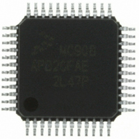
MC908AP32CFAE Freescale Semiconductor, MC908AP32CFAE Datasheet - Page 91

MC908AP32CFAE
Manufacturer Part Number
MC908AP32CFAE
Description
IC MCU 32K FLASH 8MHZ 48-LQFP
Manufacturer
Freescale Semiconductor
Series
HC08r
Specifications of MC908AP32CFAE
Core Processor
HC08
Core Size
8-Bit
Speed
8MHz
Connectivity
I²C, IRSCI, SCI, SPI
Peripherals
LED, LVD, POR, PWM
Number Of I /o
32
Program Memory Size
32KB (32K x 8)
Program Memory Type
FLASH
Ram Size
2K x 8
Voltage - Supply (vcc/vdd)
2.7 V ~ 5.5 V
Data Converters
A/D 8x10b
Oscillator Type
Internal
Operating Temperature
-40°C ~ 85°C
Package / Case
48-LQFP
Controller Family/series
HC08
No. Of I/o's
32
Ram Memory Size
2KB
Cpu Speed
8MHz
No. Of Timers
2
Embedded Interface Type
I2C, SCI, SPI
Rohs Compliant
Yes
Lead Free Status / RoHS Status
Lead free / RoHS Compliant
Eeprom Size
-
Available stocks
Company
Part Number
Manufacturer
Quantity
Price
Company:
Part Number:
MC908AP32CFAE
Manufacturer:
Freescale Semiconductor
Quantity:
10 000
Company:
Part Number:
MC908AP32CFAER
Manufacturer:
Freescale Semiconductor
Quantity:
10 000
- Current page: 91 of 316
- Download datasheet (2Mb)
6.5.2 PLL Bandwidth Control Register
The PLL bandwidth control register (PBWC):
AUTO — Automatic Bandwidth Control Bit
LOCK — Lock Indicator Bit
ACQ — Acquisition Mode Bit
Freescale Semiconductor
•
•
•
•
This read/write bit selects automatic or manual bandwidth control. When initializing the PLL for manual
operation (AUTO = 0), clear the ACQ bit before turning on the PLL. Reset clears the AUTO bit.
When the AUTO bit is set, LOCK is a read-only bit that becomes set when the VCO clock, CGMVCLK,
is locked (running at the programmed frequency). When the AUTO bit is clear, LOCK reads as logic 0
and has no meaning. The write one function of this bit is reserved for test, so this bit must always be
written a 0. Reset clears the LOCK bit.
When the AUTO bit is set, ACQ is a read-only bit that indicates whether the PLL is in acquisition mode
or tracking mode. When the AUTO bit is clear, ACQ is a read/write bit that controls whether the PLL is
in acquisition or tracking mode.
In automatic bandwidth control mode (AUTO = 1), the last-written value from manual operation is
stored in a temporary location and is recovered when manual operation resumes. Reset clears this bit,
enabling acquisition mode.
1 = Automatic bandwidth control
0 = Manual bandwidth control
1 = VCO frequency correct or locked
0 = VCO frequency incorrect or unlocked
1 = Tracking mode
0 = Acquisition mode
Selects automatic or manual (software-controlled) bandwidth control mode
Indicates when the PLL is locked
In automatic bandwidth control mode, indicates when the PLL is in acquisition or tracking mode
In manual operation, forces the PLL into acquisition or tracking mode
Address:
Reset:
Read:
Write:
$0037
AUTO
Figure 6-5. PLL Bandwidth Control Register (PBWCR)
Bit 7
0
= Unimplemented
LOCK
MC68HC908AP A-Family Data Sheet, Rev. 3
6
0
ACQ
5
0
4
0
0
R
3
0
0
= Reserved
2
0
0
1
0
0
Bit 0
R
CGM Registers
91
Related parts for MC908AP32CFAE
Image
Part Number
Description
Manufacturer
Datasheet
Request
R
Part Number:
Description:
Manufacturer:
Freescale Semiconductor, Inc
Datasheet:
Part Number:
Description:
Manufacturer:
Freescale Semiconductor, Inc
Datasheet:
Part Number:
Description:
Manufacturer:
Freescale Semiconductor, Inc
Datasheet:
Part Number:
Description:
Manufacturer:
Freescale Semiconductor, Inc
Datasheet:
Part Number:
Description:
Manufacturer:
Freescale Semiconductor, Inc
Datasheet:
Part Number:
Description:
Manufacturer:
Freescale Semiconductor, Inc
Datasheet:
Part Number:
Description:
Manufacturer:
Freescale Semiconductor, Inc
Datasheet:
Part Number:
Description:
Manufacturer:
Freescale Semiconductor, Inc
Datasheet:
Part Number:
Description:
Manufacturer:
Freescale Semiconductor, Inc
Datasheet:
Part Number:
Description:
Manufacturer:
Freescale Semiconductor, Inc
Datasheet:
Part Number:
Description:
Manufacturer:
Freescale Semiconductor, Inc
Datasheet:
Part Number:
Description:
Manufacturer:
Freescale Semiconductor, Inc
Datasheet:
Part Number:
Description:
Manufacturer:
Freescale Semiconductor, Inc
Datasheet:
Part Number:
Description:
Manufacturer:
Freescale Semiconductor, Inc
Datasheet:
Part Number:
Description:
Manufacturer:
Freescale Semiconductor, Inc
Datasheet:


