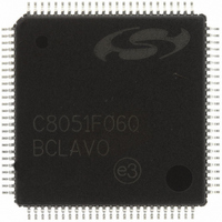
C8051F060-GQ Silicon Laboratories Inc, C8051F060-GQ Datasheet - Page 15

C8051F060-GQ
Manufacturer Part Number
C8051F060-GQ
Description
IC 8051 MCU 64K FLASH 100TQFP
Manufacturer
Silicon Laboratories Inc
Series
C8051F06xr
Specifications of C8051F060-GQ
Program Memory Type
FLASH
Program Memory Size
64KB (64K x 8)
Package / Case
100-TQFP, 100-VQFP
Core Processor
8051
Core Size
8-Bit
Speed
25MHz
Connectivity
CAN, EBI/EMI, SMBus (2-Wire/I²C), SPI, UART/USART
Peripherals
Brown-out Detect/Reset, POR, PWM, Temp Sensor, WDT
Number Of I /o
59
Ram Size
4.25K x 8
Voltage - Supply (vcc/vdd)
2.7 V ~ 3.6 V
Data Converters
A/D 2x16b, 8x10b; D/A 2x12b
Oscillator Type
Internal
Operating Temperature
-40°C ~ 85°C
Processor Series
C8051F0x
Core
8051
Data Bus Width
8 bit
Data Ram Size
4.25 KB
Interface Type
CAN/I2C/SMBus/SPI/UART
Maximum Clock Frequency
25 MHz
Number Of Programmable I/os
59
Number Of Timers
5
Operating Supply Voltage
2.7 V to 3.6 V
Maximum Operating Temperature
+ 85 C
Mounting Style
SMD/SMT
3rd Party Development Tools
PK51, CA51, A51, ULINK2
Development Tools By Supplier
C8051F060DK
Minimum Operating Temperature
- 40 C
On-chip Adc
8-ch x 10-bit
On-chip Dac
2-ch x 12-bit
No. Of I/o's
59
Ram Memory Size
4352Byte
Cpu Speed
25MHz
No. Of Timers
5
Rohs Compliant
Yes
Lead Free Status / RoHS Status
Lead free / RoHS Compliant
For Use With
336-1214 - DEV KIT FOR F060/F062/F063
Eeprom Size
-
Lead Free Status / Rohs Status
Lead free / RoHS Compliant
Other names
336-1213
Available stocks
Company
Part Number
Manufacturer
Quantity
Price
Company:
Part Number:
C8051F060-GQ
Manufacturer:
VISHAY
Quantity:
3 000
Company:
Part Number:
C8051F060-GQ
Manufacturer:
Silicon Laboratories Inc
Quantity:
10 000
Company:
Part Number:
C8051F060-GQR
Manufacturer:
Silicon Laboratories Inc
Quantity:
10 000
Company:
Part Number:
C8051F060-GQR.
Manufacturer:
SILICON
Quantity:
15 000
25. Programmable Counter Array ............................................................................. 303
26. JTAG (IEEE 1149.1) .............................................................................................. 317
27. Document Change List ........................................................................................ 327
Figure 24.6. CKCON: Clock Control Register ........................................................ 293
Figure 24.7. TL0: Timer 0 Low Byte ....................................................................... 294
Figure 24.8. TL1: Timer 1 Low Byte ....................................................................... 294
Figure 24.9. TH0: Timer 0 High Byte...................................................................... 294
Figure 24.10. TH1: Timer 1 High Byte.................................................................... 294
Figure 24.11. T2, 3, and 4 Capture Mode Block Diagram ...................................... 296
Figure 24.12. T2, 3, and 4 Auto-reload Mode Block Diagram ................................ 297
Figure 24.13. TMRnCN: Timer 2, 3, and 4 Control Registers ................................ 299
Figure 24.14. TMRnCF: Timer 2, 3, and 4 Configuration Registers ....................... 300
Figure 24.15. RCAPnL: Timer 2, 3, and 4 Capture Register Low Byte .................. 301
Figure 24.16. RCAPnH: Timer 2, 3, and 4 Capture Register High Byte................. 301
Figure 24.17. TMRnL: Timer 2, 3, and 4 Low Byte................................................. 301
Figure 24.18. TMRnH: Timer 2, 3, and 4 High Byte ............................................... 302
Figure 25.1. PCA Block Diagram............................................................................ 303
Figure 25.2. PCA Counter/Timer Block Diagram.................................................... 304
Figure 25.3. PCA Interrupt Block Diagram ............................................................. 305
Figure 25.4. PCA Capture Mode Diagram.............................................................. 306
Figure 25.5. PCA Software Timer Mode Diagram .................................................. 307
Figure 25.6. PCA High Speed Output Mode Diagram............................................ 308
Figure 25.7. PCA Frequency Output Mode ............................................................ 309
Figure 25.8. PCA 8-Bit PWM Mode Diagram ......................................................... 310
Figure 25.9. PCA 16-Bit PWM Mode...................................................................... 311
Figure 25.10. PCA0CN: PCA Control Register ...................................................... 312
Figure 25.11. PCA0MD: PCA0 Mode Register....................................................... 313
Figure 25.12. PCA0CPMn: PCA0 Capture/Compare Mode Registers................... 314
Figure 25.13. PCA0L: PCA0 Counter/Timer Low Byte........................................... 315
Figure 25.14. PCA0H: PCA0 Counter/Timer High Byte ......................................... 315
Figure 25.15. PCA0CPLn: PCA0 Capture Module Low Byte ................................. 316
Figure 25.16. PCA0CPHn: PCA0 Capture Module High Byte................................ 316
Figure 26.1. IR: JTAG Instruction Register............................................................. 317
Figure 26.2. DEVICEID: JTAG Device ID Register ................................................ 321
Figure 26.3. FLASHCON: JTAG Flash Control Register........................................ 323
Figure 26.4. FLASHDAT: JTAG Flash Data Register............................................. 324
Figure 26.5. FLASHADR: JTAG Flash Address Register....................................... 324
Rev. 1.2
C8051F060/1/2/3/4/5/6/7
15


