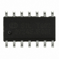
C8051T602-GS Silicon Laboratories Inc, C8051T602-GS Datasheet - Page 4

C8051T602-GS
Manufacturer Part Number
C8051T602-GS
Description
IC 8051 MCU 4K-EEPROM 14-SOIC
Manufacturer
Silicon Laboratories Inc
Series
C8051T60xr
Datasheet
1.C8051T600EDB.pdf
(188 pages)
Specifications of C8051T602-GS
Program Memory Type
OTP
Program Memory Size
4KB (4K x 8)
Package / Case
14-SOIC (3.9mm Width), 14-SOL
Core Processor
8051
Core Size
8-Bit
Speed
25MHz
Connectivity
SMBus (2-Wire/I²C), UART/USART
Peripherals
POR, PWM, Temp Sensor, WDT
Number Of I /o
8
Ram Size
256 x 8
Voltage - Supply (vcc/vdd)
1.8 V ~ 3.6 V
Data Converters
A/D 8x10b
Oscillator Type
Internal
Operating Temperature
-40°C ~ 85°C
Processor Series
C8051T6x
Core
8051
Data Bus Width
8 bit
Data Ram Size
256 B
Interface Type
I2C/SMBus/UART
Maximum Clock Frequency
25 MHz
Number Of Programmable I/os
8
Number Of Timers
3
Maximum Operating Temperature
+ 85 C
Mounting Style
SMD/SMT
3rd Party Development Tools
PK51, CA51, A51, ULINK2
Development Tools By Supplier
C8051T600DK
Minimum Operating Temperature
- 40 C
On-chip Adc
8-ch x 10-bit
Lead Free Status / RoHS Status
Lead free / RoHS Compliant
For Use With
336-1404 - KIT DEV FOR C8051T60X MCU'S
Eeprom Size
-
Lead Free Status / Rohs Status
Lead free / RoHS Compliant
Other names
336-1655-5
Available stocks
Company
Part Number
Manufacturer
Quantity
Price
Company:
Part Number:
C8051T602-GS
Manufacturer:
Silicon Labs
Quantity:
135
C8051T600/1/2/3/4/5/6
24. UART0 ................................................................................................................... 137
25. Timers ................................................................................................................... 145
26. Programmable Counter Array............................................................................. 160
27. C2 Interface .......................................................................................................... 178
4
23.4. Using the SMBus........................................................................................... 123
23.5. SMBus Transfer Modes................................................................................. 131
23.6. SMBus Status Decoding................................................................................ 134
24.1. Enhanced Baud Rate Generation.................................................................. 138
24.2. Operational Modes ........................................................................................ 139
24.3. Multiprocessor Communications ................................................................... 141
25.1. Timer 0 and Timer 1 ...................................................................................... 147
25.2. Timer 2 .......................................................................................................... 155
26.1. PCA Counter/Timer ....................................................................................... 161
26.2. PCA0 Interrupt Sources................................................................................. 162
26.3. Capture/Compare Modules ........................................................................... 163
26.4. Watchdog Timer Mode .................................................................................. 170
26.5. Register Descriptions for PCA0..................................................................... 173
27.1. C2 Interface Registers................................................................................... 178
23.3.2. Arbitration.............................................................................................. 122
23.3.3. Clock Low Extension............................................................................. 122
23.3.4. SCL Low Timeout.................................................................................. 122
23.3.5. SCL High (SMBus Free) Timeout ......................................................... 123
23.4.1. SMBus Configuration Register.............................................................. 123
23.4.2. SMB0CN Control Register .................................................................... 127
23.4.3. Data Register ........................................................................................ 130
23.5.1. Write Sequence (Master) ...................................................................... 131
23.5.2. Read Sequence (Master) ...................................................................... 132
23.5.3. Write Sequence (Slave) ........................................................................ 133
23.5.4. Read Sequence (Slave) ........................................................................ 134
24.2.1. 8-Bit UART ............................................................................................ 139
24.2.2. 9-Bit UART ............................................................................................ 140
25.1.1. Mode 0: 13-bit Counter/Timer ............................................................... 147
25.1.2. Mode 1: 16-bit Counter/Timer ............................................................... 148
25.1.3. Mode 2: 8-bit Counter/Timer with Auto-Reload..................................... 149
25.1.4. Mode 3: Two 8-bit Counter/Timers (Timer 0 Only)................................ 150
25.2.1. 16-bit Timer with Auto-Reload............................................................... 155
25.2.2. 8-bit Timers with Auto-Reload............................................................... 156
26.3.1. Edge-triggered Capture Mode............................................................... 164
26.3.2. Software Timer (Compare) Mode.......................................................... 165
26.3.3. High-Speed Output Mode ..................................................................... 166
26.3.4. Frequency Output Mode ....................................................................... 167
26.3.5. 8-bit Pulse Width Modulator Mode ....................................................... 168
26.3.6. 16-Bit Pulse Width Modulator Mode..................................................... 169
26.4.1. Watchdog Timer Operation ................................................................... 170
26.4.2. Watchdog Timer Usage ........................................................................ 171
Rev. 1.2


