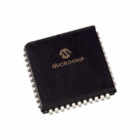
PIC16C662-04/L Microchip Technology, PIC16C662-04/L Datasheet - Page 53

PIC16C662-04/L
Manufacturer Part Number
PIC16C662-04/L
Description
IC MCU OTP 4KX14 COMP 44PLCC
Manufacturer
Microchip Technology
Series
PIC® 16Cr
Specifications of PIC16C662-04/L
Core Size
8-Bit
Program Memory Size
7KB (4K x 14)
Core Processor
PIC
Speed
4MHz
Peripherals
Brown-out Detect/Reset, LED, POR, WDT
Number Of I /o
33
Program Memory Type
OTP
Ram Size
176 x 8
Voltage - Supply (vcc/vdd)
4 V ~ 6 V
Oscillator Type
External
Operating Temperature
0°C ~ 70°C
Package / Case
44-PLCC
Controller Family/series
PIC16C
No. Of I/o's
33
Ram Memory Size
176Byte
Cpu Speed
4MHz
No. Of Timers
1
Processor Series
PIC16C
Core
PIC
Data Bus Width
8 bit
Data Ram Size
176 B
Interface Type
RS- 232
Maximum Clock Frequency
4 MHz
Number Of Programmable I/os
33
Number Of Timers
8
Operating Supply Voltage
3 V to 6 V
Maximum Operating Temperature
+ 70 C
Mounting Style
SMD/SMT
3rd Party Development Tools
52715-96, 52716-328, 52717-734
Development Tools By Supplier
ICE2000, DM163022
Minimum Operating Temperature
0 C
On-chip Adc
10 bit
Data Rom Size
176 B
Height
3.87 mm
Length
16.59 mm
Supply Voltage (max)
6 V
Supply Voltage (min)
4 V
Width
16.59 mm
Lead Free Status / RoHS Status
Lead free / RoHS Compliant
For Use With
DVA16XL441 - ADAPTER DEVICE ICE 44PLCC309-1040 - ADAPTER 44-PLCC ZIF TO 40-DIP309-1039 - ADAPTER 44-PLCC TO 40-DIP
Eeprom Size
-
Data Converters
-
Connectivity
-
Lead Free Status / Rohs Status
Details
Available stocks
Company
Part Number
Manufacturer
Quantity
Price
Company:
Part Number:
PIC16C662-04/L
Manufacturer:
Microchip Technology
Quantity:
10 000
8.0
The Voltage Reference is a 16-tap resistor ladder
network that provides a selectable voltage reference.
The resistor ladder is segmented to provide two ranges
of V
conserve power when the reference module is not
being used.
FIGURE 8-1:
FIGURE 8-2:
VREN
1996 Microchip Technology Inc.
bit7
bit 7:
bit 6:
bit 5:
bit 4:
bit 3-0: VR3:VR0 : V
R/W-0
VREN
Note:
REF
VOLTAGE REFERENCE
MODULE
values and has a power-down function to
VREN: V
1 = V
0 = V
VROE: V
1 = V
0 = V
VRR: V
1 = Low Range
0 = High Range
Unimplemented: Read as '0'
When: VRR = 1
Then: V
When: VRR = 0
Then: V
R is defined in Table 12-3.
R/W-0
VROE
REF
REF
REF
REF
V
VOLTAGE REFERENCE BLOCK DIAGRAM
VRCON REGISTER (ADDRESS 9Fh)
REF
REF
REF
REF
REF
REF
circuit powered up
circuit powered down, no I
is output on RA2 pin
is disconnected from RA2 pin
Range selection
= (VR3:VR0/ 24) • V
= 1/4 • V
REF
R/W-0
Enable
Output Enable
VRR
value selection 0
This document was created with FrameMaker 4 0 4
8R
DD
U-0
—
+ (VR3:VR0/ 32) • V
R
R/W-0
VR3
DD
DD
VR3:VR0
R
Preliminary
drain
PIC16C64X & PIC16C66X
R/W-0
VR2
16 Stages
DD
16-1 Analog Mux
15
The VRCON register, shown in Figure 8-1, controls the
operation of the Voltage Reference Module. The block
diagram is given in Figure 8-2.
R/W-0
VR1
R
bit0
R/W-0
VR0
R
R =Readable bit
W =Writable bit
U =Unimplemented bit, read
as ‘0’
- n =Value at POR reset
8R
VR3
VR2
VR1
VR0
(From VRCON<3:0>)
DS30559A-page 53
VRR


