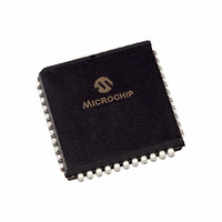
PIC16LC74B-04/L Microchip Technology, PIC16LC74B-04/L Datasheet - Page 173

PIC16LC74B-04/L
Manufacturer Part Number
PIC16LC74B-04/L
Description
IC MCU OTP 4KX14 A/D PWM 44PLCC
Manufacturer
Microchip Technology
Series
PIC® 16Cr
Specifications of PIC16LC74B-04/L
Core Processor
PIC
Core Size
8-Bit
Speed
4MHz
Connectivity
I²C, SPI, UART/USART
Peripherals
Brown-out Detect/Reset, POR, PWM, WDT
Number Of I /o
33
Program Memory Size
7KB (4K x 14)
Program Memory Type
OTP
Ram Size
192 x 8
Voltage - Supply (vcc/vdd)
2.5 V ~ 5.5 V
Data Converters
A/D 5x8b
Oscillator Type
External
Operating Temperature
0°C ~ 70°C
Package / Case
44-PLCC
Lead Free Status / RoHS Status
Lead free / RoHS Compliant
Eeprom Size
-
Available stocks
Company
Part Number
Manufacturer
Quantity
Price
Company:
Part Number:
PIC16LC74B-04/L
Manufacturer:
MICROCHIP
Quantity:
6 237
Company:
Part Number:
PIC16LC74B-04/L
Manufacturer:
Microchip Technology
Quantity:
10 000
Timing Diagrams
Timing Diagrams and Specifications................................. 124
TMR0 Register .................................................................... 17
TMR1CS bit ........................................................................ 43
TMR1H Register ................................................................. 17
TMR1L Register .................................................................. 17
TMR1ON bit ........................................................................ 43
TMR2 Register .................................................................... 17
TMR2ON bit ........................................................................ 47
TO bit .................................................................................. 19
TOUTPS0 bit....................................................................... 47
TOUTPS1 bit....................................................................... 47
TOUTPS2 bit....................................................................... 47
TOUTPS3 bit....................................................................... 47
TRISA Register ............................................................. 18, 29
TRISB Register ............................................................. 18, 31
TRISC Register ............................................................. 18, 33
TRISD Register ............................................................. 18, 34
TRISE Register ....................................................... 18, 35, 36
TXSTA Register .................................................................. 65
2000 Microchip Technology Inc.
Timer2
I
SPI Master Mode ........................................................ 58
SPI Slave Mode (CKE = 1) ......................................... 59
SPI Slave Mode Timing (CKE = 0).............................. 58
USART Asynchronous Master Transmission.............. 69
USART Asynchronous Reception............................... 71
USART Synchronous Reception................................. 75
USART Synchronous Transmission............................ 73
Wake-up from SLEEP via Interrupt ............................. 98
A/D Conversion......................................................... 138
Brown-out Reset (BOR) ............................................ 126
Capture/Compare/PWM (CCP)................................. 128
CLKOUT and I/O....................................................... 125
External Clock........................................................... 124
I
I
Oscillator Start-up Timer (OST)................................. 126
Parallel Slave Port (PSP).......................................... 129
Power-up Timer (PWRT)........................................... 126
RESET ...................................................................... 126
Timer0 and Timer1.................................................... 127
USART Synchronous Receive (Master/Slave) ......... 136
USART SynchronousTransmission (Master/Slave) .. 136
Watchdog Timer (WDT) ............................................ 126
2
2
2
C Reception (7-bit Address) ..................................... 62
C Bus Data ............................................................. 134
C Bus START/STOP Bits ....................................... 134
TMR1H ............................................................... 45
TMR1L ................................................................ 45
Block Diagram .................................................... 47
Module ................................................................ 47
Postscaler ........................................................... 47
Prescaler............................................................. 47
T2CON................................................................ 47
PIC16C63A/65B/73B/74B
U
UA....................................................................................... 56
Universal Synchronous Asynchronous Receiver
Transmitter (USART) .......................................................... 65
Update Address bit, UA ...................................................... 56
USART
UV Erasable Devices............................................................ 7
W
Wake-up from SLEEP......................................................... 97
Watchdog Timer (WDT).................................... 85, 87, 90, 95
WCOL ................................................................................. 57
WDT ................................................................................... 90
WR pin ................................................................................ 37
Write Collision Detect bit, WCOL........................................ 57
WWW, On-Line Support ....................................................... 3
Z
Z bit..................................................................................... 19
Asynchronous Mode................................................... 68
Asynchronous Receiver.............................................. 70
Asynchronous Reception............................................ 71
Asynchronous Transmitter.......................................... 68
Baud Rate Generator (BRG) ...................................... 67
Receive Block Diagram .............................................. 70
Sampling..................................................................... 67
Synchronous Master Mode......................................... 72
Synchronous Master Reception ................................. 74
Synchronous Master Transmission ............................ 72
Synchronous Slave Mode........................................... 76
Synchronous Slave Reception ................................... 76
Synchronous Slave Transmit...................................... 76
Transmit Block Diagram ............................................. 68
Timing Diagram ........................................................ 126
Block Diagram ............................................................ 96
Period ......................................................................... 95
Programming Considerations ..................................... 96
Time-out...................................................................... 91
Timing Diagram, Synchronous Receive ........... 136
Timing Diagram, Synchronous Transmission... 136
DS30605C-page 173


