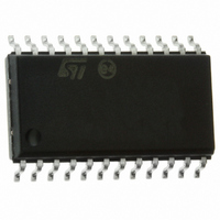
ST72F63BE6M1 STMicroelectronics, ST72F63BE6M1 Datasheet - Page 102

ST72F63BE6M1
Manufacturer Part Number
ST72F63BE6M1
Description
IC MCU 8BIT 32K FLASH 24-SOIC
Manufacturer
STMicroelectronics
Series
ST7r
Datasheet
1.ST72F63BD6U1TR.pdf
(186 pages)
Specifications of ST72F63BE6M1
Core Processor
ST7
Core Size
8-Bit
Speed
8MHz
Connectivity
I²C, SCI, USB
Peripherals
DMA, LVD, POR, PWM, WDT
Number Of I /o
14
Program Memory Size
32KB (32K x 8)
Program Memory Type
FLASH
Ram Size
1K x 8
Voltage - Supply (vcc/vdd)
4 V ~ 5.5 V
Oscillator Type
External
Operating Temperature
0°C ~ 70°C
Package / Case
24-SOIC (7.5mm Width)
Data Converters
A/D 12x8b
Processor Series
ST72F6x
Core
ST7
Data Bus Width
8 bit
Data Ram Size
1 KB
Interface Type
I2C, SCI
Maximum Clock Frequency
8 MHz
Number Of Programmable I/os
14
Number Of Timers
1
Maximum Operating Temperature
+ 70 C
Mounting Style
SMD/SMT
Development Tools By Supplier
ST72F63B-SK/RAIS, ST7MDTU3-EMU3, STX-RLINK
Minimum Operating Temperature
0 C
For Use With
497-5521 - EVAL BOARD LOW SPEED USB
Lead Free Status / RoHS Status
Lead free / RoHS Compliant
Eeprom Size
-
Lead Free Status / Rohs Status
Details
Available stocks
Company
Part Number
Manufacturer
Quantity
Price
- Current page: 102 of 186
- Download datasheet (3Mb)
On-chip peripherals
Note:
102/186
To avoid spurious clearing of some bits, it is recommended to clear them using a load
instruction where all bits which must not be altered are set, and all bits to be cleared are
reset. Avoid read-modify-write instructions like AND, XOR.
Interrupt Mask register (IMR)
These bits are mask bits for all interrupt condition bits included in the ISTR. Whenever one
of the IMR bits is set, if the corresponding ISTR bit is set, and the I bit in the CC register is
cleared, an interrupt request is generated. For an explanation of each bit, please refer to the
corresponding bit description in ISTR.
Reset value: 0000 0000 (00h)
SUSPM
7
2 ESUSP End suspend mode.
1 RESET USB reset.
0 SOF Start of frame.
DOVRM
This bit is set by hardware when, during suspend mode, activity is detected that
wakes the USB interface up from suspend mode.
This interrupt is serviced by a specific vector, in order to wake up the ST7 from Halt
mode.
0: No End Suspend detected
1: End Suspend detected
This bit is set by hardware when the USB reset sequence is detected on the bus.
0: No USB reset signal detected
1: USB reset signal detected
Note: The DADDR, EP0RA, EP0RB, EP1RA, EP1RB, EP2RA and EP2RB
This bit is set by hardware when a low-speed SOF indication (keep-alive strobe) is
seen on the USB bus. It is also issued at the end of a resume sequence.
0: No SOF signal detected
1: SOF signal detected
registers are reset by a USB reset.
CTRM
Doc ID 7516 Rev 8
ERRM
Read.write
IOVRM
ESUSPM
RESETM
ST7263Bxx
SOFM
0
Related parts for ST72F63BE6M1
Image
Part Number
Description
Manufacturer
Datasheet
Request
R

Part Number:
Description:
KIT STARTER LOW COST ST7
Manufacturer:
STMicroelectronics
Datasheet:

Part Number:
Description:
LOW SPEED USB 8-BIT MCU FAMILY WITH FLASH/ROM, UP TO 512 BYTES RAM, 8-BIT ADC, WDG, TIMER, SCI & I²C
Manufacturer:
STMICROELECTRONICS [STMicroelectronics]
Datasheet:

Part Number:
Description:
STMicroelectronics [RIPPLE-CARRY BINARY COUNTER/DIVIDERS]
Manufacturer:
STMicroelectronics
Datasheet:

Part Number:
Description:
STMicroelectronics [LIQUID-CRYSTAL DISPLAY DRIVERS]
Manufacturer:
STMicroelectronics
Datasheet:

Part Number:
Description:
BOARD EVAL FOR MEMS SENSORS
Manufacturer:
STMicroelectronics
Datasheet:

Part Number:
Description:
NPN TRANSISTOR POWER MODULE
Manufacturer:
STMicroelectronics
Datasheet:

Part Number:
Description:
TURBOSWITCH ULTRA-FAST HIGH VOLTAGE DIODE
Manufacturer:
STMicroelectronics
Datasheet:

Part Number:
Description:
Manufacturer:
STMicroelectronics
Datasheet:

Part Number:
Description:
DIODE / SCR MODULE
Manufacturer:
STMicroelectronics
Datasheet:

Part Number:
Description:
DIODE / SCR MODULE
Manufacturer:
STMicroelectronics
Datasheet:

Part Number:
Description:
Search -----> STE16N100
Manufacturer:
STMicroelectronics
Datasheet:

Part Number:
Description:
Search ---> STE53NA50
Manufacturer:
STMicroelectronics
Datasheet:


