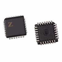
Z86E3412VSC Zilog, Z86E3412VSC Datasheet - Page 60

Z86E3412VSC
Manufacturer Part Number
Z86E3412VSC
Description
IC MICROCONTROLLER 16K 28-PLCC
Manufacturer
Zilog
Series
Z8®r
Datasheet
1.Z86E3312SSC.pdf
(84 pages)
Specifications of Z86E3412VSC
Core Processor
Z8
Core Size
8-Bit
Speed
12MHz
Connectivity
EBI/EMI
Peripherals
POR, WDT
Number Of I /o
24
Program Memory Size
16KB (16K x 8)
Program Memory Type
OTP
Ram Size
237 x 8
Voltage - Supply (vcc/vdd)
3.5 V ~ 5.5 V
Oscillator Type
Internal
Operating Temperature
0°C ~ 70°C
Package / Case
28-PLCC
Data Bus Width
8 bit
Data Ram Size
237 B
Maximum Clock Frequency
12 MHz
Number Of Programmable I/os
24
Number Of Timers
2 bit
Operating Supply Voltage
3.5 V to 5.5 V
Maximum Operating Temperature
+ 70 C
Mounting Style
SMD/SMT
Minimum Operating Temperature
0 C
Lead Free Status / RoHS Status
Contains lead / RoHS non-compliant
Eeprom Size
-
Data Converters
-
Lead Free Status / Rohs Status
No
Other names
269-1039
Available stocks
Company
Part Number
Manufacturer
Quantity
Price
PS022901-0508
C1
C2
Ceramic Resonator or Crystal
C1, C2 = 33 pF
f = 8 MHz
* Typical value including pin parasitics
XTAL1
XTAL2
Power-On Reset (POR). A timer circuit clocked by a dedicated on-board RC oscillator is
used for the Power-On Reset (POR) timer function. The POR timer allows V
oscillator circuit to stabilize before instruction execution begins.
The POR timer circuit is a one-shot timer triggered by one of three conditions:
1. Power fail to Power OK status
2. Stop Mode Recovery (if D5 of SMR=0)
3. WDT time-out
The POR time is a nominal 5 ms. Bit 5 of the STOP mode Register (SMR) determines
whether the POR timer is by-passed after Stop Mode Recovery (typical for an external
clock and RC/LC oscillators with fast start up times).
HALT. Turns off the internal CPU clock, but not the XTAL oscillation. The counter/timers
and external interrupt IRQ0, IRQ1, and IRQ2 remain active. The device is recovered by
interrupts, either externally or internally generated. An interrupt request must be executed
(enabled) to exit HALT Mode. After the interrupt service routine, the program continues
from the instruction after the HALT. In order to enter STOP or HALT Mode, it is neces-
sary to first flush the instruction pipeline to avoid suspending execution in mid-instruc-
tion. To do this, you must execute a NOP (Opcode = FFh) immediately before the
appropriate sleep instruction, that is:
TYP *
Figure 29. Oscillator Configuration
V
SS
C1
C2
LC
C1, C2 = 22 pF
**
L = 130 μH *
f = 3 MHz
L
XTAL1
XTAL2
C1
CMOS Z8
@ 5V V
C1 = 100 pF *
R = 2K *
RC
f = 6 MHz *
R
CC
®
(TYP)
Product Specification
OTP Microcontrollers
XTAL1
XTAL2
Electrical Characteristics
CC
External Clock
and the
XTAL1
XTAL2
56


