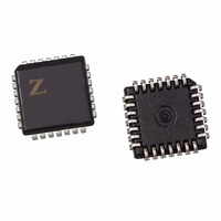
Z86E3412VSC Zilog, Z86E3412VSC Datasheet - Page 66

Z86E3412VSC
Manufacturer Part Number
Z86E3412VSC
Description
IC MICROCONTROLLER 16K 28-PLCC
Manufacturer
Zilog
Series
Z8®r
Datasheet
1.Z86E3312SSC.pdf
(84 pages)
Specifications of Z86E3412VSC
Core Processor
Z8
Core Size
8-Bit
Speed
12MHz
Connectivity
EBI/EMI
Peripherals
POR, WDT
Number Of I /o
24
Program Memory Size
16KB (16K x 8)
Program Memory Type
OTP
Ram Size
237 x 8
Voltage - Supply (vcc/vdd)
3.5 V ~ 5.5 V
Oscillator Type
Internal
Operating Temperature
0°C ~ 70°C
Package / Case
28-PLCC
Data Bus Width
8 bit
Data Ram Size
237 B
Maximum Clock Frequency
12 MHz
Number Of Programmable I/os
24
Number Of Timers
2 bit
Operating Supply Voltage
3.5 V to 5.5 V
Maximum Operating Temperature
+ 70 C
Mounting Style
SMD/SMT
Minimum Operating Temperature
0 C
Lead Free Status / RoHS Status
Contains lead / RoHS non-compliant
Eeprom Size
-
Data Converters
-
Lead Free Status / Rohs Status
No
Other names
269-1039
Available stocks
Company
Part Number
Manufacturer
Quantity
Price
PS022901-0508
Note:
Reset and initially enabled by executing the WDT instruction and refreshed on subsequent
executions of the WDT instruction. The WDT is driven either by an on-board RC oscilla-
tor or an external oscillator from XTAL1 pin. The POR clock source is selected with bit 4
of the WDT register.
WDT Time-Out Period (D0 and D1). Bits 0 and 1 control a tap circuit that determines
the time-out periods that can be obtained
and 0, respectively.
Table 23. Time-out Period of WDT
WDT During HALT Mode (D2). This bit determines whether or not the WDT is active
during HALT Mode. A “1” indicates that the WDT is active during HALT. A “0” disables
the WDT in HALT Mode. The default value is “1 “. WDT During STOP Mode (D3). This
bit determines whether or not the WDT is active during STOP mode. A “1” indicates
active during STOP. A “0” disables the WDT during STOP Mode. This is applicable only
when the WDT clock source is the internal RC oscillator.
Clock Source For WDT (D4). This bit determines which oscillator source is used to
clock the internal POR and WDT counter chain. If the bit is a 1, the internal RC oscillator
is bypassed and the POR and WDT clock source is driven from the external pin, XTAL1,
and the WDT is stopped in STOP Mode. The default configuration of this bit is 0, which
selects the RC oscillator.
Permanent WDT. When this feature is enabled, the WDT is enabled after reset and will
operate in Run and HALT Mode. The control bits in the WDTMR do not affect the WDT
operation. If the clock source of the WDT is the internal RC oscillator, then the WDT will
run in STOP mode. If the clock source of the WDT is the XTAL1 pin, then the WDT will
not run in STOP mode.
D1
0
0
1
1
Note: The default setting is 10 ms.
Execution of the WDT instruction affects the Z (Zero), S (Sign), and V
(Overflow) flags.
DO
0
1
0
1
Time-out of the
Internal RC
OSC
5 ms
10 ms
20 ms
80 ms
1
(Table
Time-out of the
System Clock
128 SCLK
256 SCLK
512 SCLK
2048 SCLK
23). The default value of DO and Dl are 1
CMOS Z8
1
®
Product Specification
OTP Microcontrollers
Electrical Characteristics
62


