MC9S08AC48CFDE Freescale Semiconductor, MC9S08AC48CFDE Datasheet - Page 180
MC9S08AC48CFDE
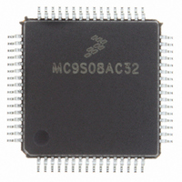
Manufacturer Part Number
MC9S08AC48CFDE
Description
IC MCU 8BIT 48K FLASH 48-QFN
Manufacturer
Freescale Semiconductor
Series
HCS08r
Datasheet
1.MC9S08AC60CFJE.pdf
(348 pages)
Specifications of MC9S08AC48CFDE
Core Processor
HCS08
Core Size
8-Bit
Speed
40MHz
Connectivity
I²C, SCI, SPI
Peripherals
LVD, POR, PWM, WDT
Number Of I /o
38
Program Memory Size
48KB (48K x 8)
Program Memory Type
FLASH
Ram Size
2K x 8
Voltage - Supply (vcc/vdd)
2.7 V ~ 5.5 V
Data Converters
A/D 8x10b
Oscillator Type
Internal
Operating Temperature
-40°C ~ 85°C
Package / Case
48-QFN
Processor Series
S08AC
Core
HCS08
Data Bus Width
8 bit
Data Ram Size
2 KB
Interface Type
I2C, SCI, SPI
Operating Supply Voltage
- 0.3 V to + 5.8 V
Maximum Operating Temperature
+ 125 C
Mounting Style
SMD/SMT
3rd Party Development Tools
EWS08
Development Tools By Supplier
DEMO9S08AC60E, DEMOACEX, DEMOACKIT, DCF51AC256, DC9S08AC128, DC9S08AC16, DC9S08AC60, DEMO51AC256KIT
Minimum Operating Temperature
- 40 C
On-chip Adc
10 bit, 8 Channel
Lead Free Status / RoHS Status
Lead free / RoHS Compliant
Eeprom Size
-
Lead Free Status / Rohs Status
Lead free / RoHS Compliant
Available stocks
Company
Part Number
Manufacturer
Quantity
Price
Company:

Part Number:
MC9S08AC48CFDE
Manufacturer:
INTEL
Quantity:
210


Chapter 10 Internal Clock Generator (S08ICGV4)
10.5.11 Fixed Frequency Clock
The ICG provides a fixed frequency clock output, XCLK, for use by on-chip peripherals. This output is
equal to the internal bus clock, BUSCLK, in all modes except FEE. In FEE mode, XCLK is equal to
ICGERCLK ÷ 2 when the following conditions are met:
If the above conditions are not true, then XCLK is equal to BUSCLK.
When the ICG is in either FEI or SCM mode, XCLK is turned off. Any peripherals which can use XCLK
as a clock source must not do so when the ICG is in FEI or SCM mode.
10.5.12 High Gain Oscillator
The oscillator has the option of running in a high gain oscillator (HGO) mode, which improves the
oscillator's resistance to EMC noise when running in FBE or FEE modes. This option is selected by writing
a 1 to the HGO bit in the ICGC1 register. HGO is used with both the high and low range oscillators but is
only valid when REFS = 1 in the ICGC1 register. When HGO = 0, the standard low-power oscillator is
selected. This bit is writable only once after any reset.
10.6
10.6.1
The section is intended to give some basic direction on which configuration a user would want to select
when initializing the ICG. For some applications, the serial communication link may dictate the accuracy
of the clock reference. For other applications, lowest power consumption may be the chief clock
consideration. Still others may have lowest cost as the primary goal. The ICG allows great flexibility in
choosing which is best for any application.
180
•
•
(P × N) ÷ R ≥ 4 where P is determined by RANGE (see
MFD and RFD respectively (see
LOCK = 1.
Initialization/Application Information
Introduction
MC9S08AC60 Series Data Sheet, Rev. 2
Table
10-12).
Table
10-11), N and R are determined by
Freescale Semiconductor
Related parts for MC9S08AC48CFDE
Image
Part Number
Description
Manufacturer
Datasheet
Request
R

Part Number:
Description:
Manufacturer:
Freescale Semiconductor, Inc
Datasheet:
Part Number:
Description:
Manufacturer:
Freescale Semiconductor, Inc
Datasheet:
Part Number:
Description:
Manufacturer:
Freescale Semiconductor, Inc
Datasheet:
Part Number:
Description:
Manufacturer:
Freescale Semiconductor, Inc
Datasheet:
Part Number:
Description:
Manufacturer:
Freescale Semiconductor, Inc
Datasheet:
Part Number:
Description:
Manufacturer:
Freescale Semiconductor, Inc
Datasheet:
Part Number:
Description:
Manufacturer:
Freescale Semiconductor, Inc
Datasheet:
Part Number:
Description:
Manufacturer:
Freescale Semiconductor, Inc
Datasheet:
Part Number:
Description:
Manufacturer:
Freescale Semiconductor, Inc
Datasheet:
Part Number:
Description:
Manufacturer:
Freescale Semiconductor, Inc
Datasheet:
Part Number:
Description:
Manufacturer:
Freescale Semiconductor, Inc
Datasheet:
Part Number:
Description:
Manufacturer:
Freescale Semiconductor, Inc
Datasheet:
Part Number:
Description:
Manufacturer:
Freescale Semiconductor, Inc
Datasheet:
Part Number:
Description:
Manufacturer:
Freescale Semiconductor, Inc
Datasheet:
Part Number:
Description:
Manufacturer:
Freescale Semiconductor, Inc
Datasheet: