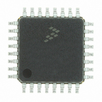
MC56F8011VFAE Freescale Semiconductor, MC56F8011VFAE Datasheet - Page 116

MC56F8011VFAE
Manufacturer Part Number
MC56F8011VFAE
Description
IC DIGITAL SIGNAL CTLR 32-LQFP
Manufacturer
Freescale Semiconductor
Series
56F8xxxr
Datasheet
1.MC56F8013VFAE.pdf
(126 pages)
Specifications of MC56F8011VFAE
Core Processor
56800
Core Size
16-Bit
Speed
32MHz
Connectivity
I²C, SCI, SPI
Peripherals
POR, PWM, WDT
Number Of I /o
26
Program Memory Size
12KB (6K x 16)
Program Memory Type
FLASH
Ram Size
1K x 16
Voltage - Supply (vcc/vdd)
3 V ~ 3.6 V
Data Converters
A/D 6x12b
Oscillator Type
Internal
Operating Temperature
-40°C ~ 105°C
Package / Case
32-LQFP
Product
DSCs
Data Bus Width
16 bit
Processor Series
MC56F80xx
Core
56800E
Numeric And Arithmetic Format
Fixed-Point
Device Million Instructions Per Second
32 MIPs
Maximum Clock Frequency
32 MHz
Number Of Programmable I/os
26
Data Ram Size
2 KB
Operating Supply Voltage
3.3 V
Maximum Operating Temperature
+ 105 C
Mounting Style
SMD/SMT
Development Tools By Supplier
MC56F8037EVM, DEMO56F8014-EE, DEMO56F8013-EE
Interface Type
SCI, SPI, I2C
Minimum Operating Temperature
- 40 C
For Use With
CPA56F8013 - BOARD SOCKET FOR MC56F8013APMOTOR56F8000E - KIT DEMO MOTOR CTRL SYSTEM
Lead Free Status / RoHS Status
Lead free / RoHS Compliant
Eeprom Size
-
Lead Free Status / Rohs Status
Lead free / RoHS Compliant
Available stocks
Company
Part Number
Manufacturer
Quantity
Price
Company:
Part Number:
MC56F8011VFAE
Manufacturer:
Freescale
Quantity:
1
Company:
Part Number:
MC56F8011VFAE
Manufacturer:
Freescale Semiconductor
Quantity:
10 000
10.16 Power Consumption
See
detail which can be used to optimize power consumption for a given application.
Power consumption is given by the following equation:
A, the internal [static component], is comprised of the DC bias currents for the oscillator, leakage currents,
PLL, and voltage references. These sources operate independently of processor state or operating
116
Total power =
Please see http://www.freescale.com for the most current mechanical drawing.
1.
2.
3.
4.
5.
6.
Section 10.1
ADC Input
Parasitic capacitance due to package, pin-to-pin and pin-to-package
base coupling; 1.8pF
Parasitic capacitance due to the chip bond pad, ESD protection devices
and signal routing; 2.04pF
8 pF noise damping capacitor
C1 = 1.4 pF
S1 and S2 switch phases are non-overlapping and operate at the ADC
clock frequency
Equivalent input impedance, when the input is selected =
Equivalent Circuit for A/D Loading
1
S1
S2
for a list of IDD requirements for the 56F8013/56F8011. This section provides additional
+D: external [dynamic component]
+B: internal [state-dependent component]
+C: internal [dynamic component]
+E: external [static]
A: internal [static component]
2
Figure 10-17 Equivalent Circuit for A/D Loading
125 Ohm
ESD Resistor
56F8013/56F8011 Data Sheet, Rev. 12
3
(V
channel mux
equiv resistance
100 Ohms
REFHx
(
ADC
- V
REFLx
Clock
) / 2
Rate
1
)
×
S1
S1
1
4 .
S2
×
10
−
12
S2
+
C1
C1
100
ohm
C1
2 X C1 : Differential Mode
C1
2 X C1 : Differential Mode
+
125
Freescale Semiconductor
S/H
: Singled Ended Mode
: Singled Ended Mode
S1
S1
ohm


