MCF51EM256CLL Freescale Semiconductor, MCF51EM256CLL Datasheet - Page 416
MCF51EM256CLL
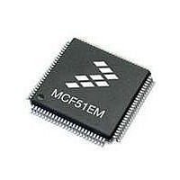
Manufacturer Part Number
MCF51EM256CLL
Description
IC MCU 32BIT 256KB FLASH 100LQFP
Manufacturer
Freescale Semiconductor
Series
MCF51EMr
Datasheets
1.MCF51EM128CLL.pdf
(2 pages)
2.MCF51EM128CLL.pdf
(54 pages)
3.MCF51EM128CLL.pdf
(636 pages)
Specifications of MCF51EM256CLL
Core Processor
Coldfire V1
Core Size
32-Bit
Speed
50MHz
Connectivity
I²C, SCI, SPI
Peripherals
LCD, LVD, PWM, WDT
Number Of I /o
63
Program Memory Size
256KB (256K x 8)
Program Memory Type
FLASH
Ram Size
16K x 8
Voltage - Supply (vcc/vdd)
1.8 V ~ 3.6 V
Data Converters
A/D 16x12b
Oscillator Type
External
Operating Temperature
-40°C ~ 85°C
Package / Case
100-LQFP
Processor Series
MCF51EM
Core
ColdFire V1
Data Bus Width
32 bit
Data Ram Size
16 KB
Interface Type
RS-232, LIN
Maximum Clock Frequency
50 MHz
Number Of Timers
3
Operating Supply Voltage
1.8 V to 3.6 V
Maximum Operating Temperature
+ 85 C
Mounting Style
SMD/SMT
3rd Party Development Tools
JLINK-CF-BDM26, EWCF
Development Tools By Supplier
DEMOEM
Minimum Operating Temperature
- 40 C
Lead Free Status / RoHS Status
Lead free / RoHS Compliant
Eeprom Size
-
Lead Free Status / Rohs Status
Lead free / RoHS Compliant
Available stocks
Company
Part Number
Manufacturer
Quantity
Price
Company:

Part Number:
MCF51EM256CLL
Manufacturer:
FREESCALE
Quantity:
110
Company:
Part Number:
MCF51EM256CLL
Manufacturer:
Freescale Semiconductor
Quantity:
10 000


Independent Robust Real Time Clock (IRTC)
17.5.22 IRTC Tamper Time Stamp Seconds Register (IRTC_TTSR_SEC)
This register is a used to store the value of seconds counter when a tamper is detected. This register serves
as a purpose for CPU to know when a tamper had occurred. This register is has no effect on software reset.
The value shown in this register is for recent tamper detection only. Previous intrusions cannot be detected.
In BCD mode, the value of seconds counter is shown in that format.
The tamper status bits indicate the reason for tamper to the CPU. These bits are valid when the interrupt
status bit is set in the IRTC_ISR and cleared when the interrupt status bit is cleared. The reset value is “11”
as POR is generated when both mains and battery supply are down, which can be due to tampering. The
CPU can take appropriate action based on this. After calibration, CPU should clear these bits and the
interrupt status bit. Writing to this register has no effect and is a read only register.
17-32
Reset Value
Reset Value
Field (bcd)
Field (bcd)
Field (bin)
Field (bin)
Bit Type
Bit Type
IRTC_TTSR_SEC
15–10
Field
9–8
7–6
5–0
Figure 17-23. IRTC Tamper Time Stamp Seconds Register (IRTC_TTSR_SEC)
MCF51EM256 Series ColdFire Integrated Microcontroller Reference Manual, Rev. 8
Reserved bits. Not writeable. Read returns zeros.
Tamper Detect Status. Indicates the type of tamper detected. Value is valid when tamper interrupt status
bit is set. Read only Bits that reset on tamper interrupt status bit being acknowledged.
00 – No tamper detected
01 – Tamper detected via external signal
10 – Battery disconnected when MCU power is ON
11 – Battery disconnected when MCU power is OFF
Reserved bits in Binary mode. Read returns zeros. In BCD mode, these are used.
Tamper Detect Seconds Value. Count: 0 – 59
Bit 15
rsvd
rsvd
Bit 7
—
—
TIME STAMP SECONDS (tens)
Table 17-25. IRTC_TTSR_SEC Field Descriptions
Bit 14
rsvd
rsvd
Bit 6
—
—
Bit 13
rsvd
Bit 5
Tamper Time Stamp Seconds Register
—
ro
0
Bit 12
rsvd
Bit 4
—
ro
0
Description
TIME STAMP SECONDS
Bit 11
rsvd
Bit 3
—
ro
0
TIME STAMP SECONDS (units)
Bit 10
rsvd
Bit 2
—
ro
0
Bit 9
Bit 1
Value in Binary
ro
ro
1
0
STATUS
Freescale Semiconductor
Bit 8
Bit 0
Offset: 0x30
ro
ro
1
0
0x30
0x31
Related parts for MCF51EM256CLL
Image
Part Number
Description
Manufacturer
Datasheet
Request
R

Part Number:
Description:
BOARD DEMO HARDWARE ONLY
Manufacturer:
Freescale Semiconductor
Datasheet:

Part Number:
Description:
IC MCU 32BIT 128KB FLASH 100LQFP
Manufacturer:
Freescale Semiconductor
Datasheet:

Part Number:
Description:
IC MCU 32BIT 128KB FLASH 80LQFP
Manufacturer:
Freescale Semiconductor
Datasheet:
Part Number:
Description:
IC MCU 32BIT 256KB FLASH 80LQFP
Manufacturer:
Freescale Semiconductor
Datasheet:


Part Number:
Description:
Manufacturer:
Freescale Semiconductor, Inc
Datasheet:
Part Number:
Description:
Manufacturer:
Freescale Semiconductor, Inc
Datasheet:
Part Number:
Description:
Manufacturer:
Freescale Semiconductor, Inc
Datasheet:
Part Number:
Description:
Manufacturer:
Freescale Semiconductor, Inc
Datasheet:
Part Number:
Description:
Manufacturer:
Freescale Semiconductor, Inc
Datasheet:
Part Number:
Description:
Manufacturer:
Freescale Semiconductor, Inc
Datasheet:
Part Number:
Description:
Manufacturer:
Freescale Semiconductor, Inc
Datasheet:
Part Number:
Description:
Manufacturer:
Freescale Semiconductor, Inc
Datasheet:
Part Number:
Description:
Manufacturer:
Freescale Semiconductor, Inc
Datasheet:
Part Number:
Description:
Manufacturer:
Freescale Semiconductor, Inc
Datasheet: