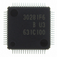
M30281F6HP#U3B Renesas Electronics America, M30281F6HP#U3B Datasheet - Page 13

M30281F6HP#U3B
Manufacturer Part Number
M30281F6HP#U3B
Description
IC M16C/28 MCU FLASH 48K 64LQFP
Manufacturer
Renesas Electronics America
Series
M16C™ M16C/Tiny/28r
Datasheet
1.M30280F6HPU9.pdf
(425 pages)
Specifications of M30281F6HP#U3B
Core Processor
M16C/60
Core Size
16-Bit
Speed
20MHz
Connectivity
I²C, IEBus, SIO, UART/USART
Peripherals
DMA, POR, PWM, Voltage Detect, WDT
Number Of I /o
55
Program Memory Size
48KB (48K x 8)
Program Memory Type
FLASH
Ram Size
4K x 8
Voltage - Supply (vcc/vdd)
2.7 V ~ 5.5 V
Data Converters
A/D 13x10b
Oscillator Type
Internal
Operating Temperature
-40°C ~ 85°C
Package / Case
64-LQFP
For Use With
R0K330290S000BE - KIT EVAL STARTER FOR M16C/29M30290T2-CPE - EMULATOR COMPACT M16C/26A/28/29M30290T2-CPE-HP - EMULATOR COMPACT FOR M16C/TINY
Lead Free Status / RoHS Status
Lead free / RoHS Compliant
Eeprom Size
-
Available stocks
Company
Part Number
Manufacturer
Quantity
Price
Part Number:
M30281F6HP#U3BM30281F6HP#D5
Manufacturer:
Renesas Electronics America
Quantity:
10 000
Part Number:
M30281F6HP#U3BM30281F6HP#U3
Manufacturer:
Renesas Electronics America
Quantity:
10 000
- Current page: 13 of 425
- Download datasheet (4Mb)
13. Timer S .......................................................................................................135
14. Serial I/O ....................................................................................................165
15. A/D Converter .............................................................................................217
12.2 Timer B ...................................................................................................................... 114
12.3 Three-phase Motor Control Timer Function ................................................................ 122
13.1 Base Timer ................................................................................................................. 146
13.2 Interrupt Operation ..................................................................................................... 151
13.3 DMA Support .............................................................................................................. 151
13.4 Time Measurement Function ...................................................................................... 152
13.5 Waveform Generating Function .................................................................................. 156
13.6 I/O Port Function Select ............................................................................................. 163
14.1 UARTi (i=0 to 2) .......................................................................................................... 165
14.2 SI/O3 and SI/O4 ........................................................................................................ 212
15.1 Operating Modes ........................................................................................................ 223
12.2.1 Timer Mode ......................................................................................................... 116
12.2.2 Event Counter Mode ............................................................................................ 117
12.2.3 Pulse Period and Pulse Width Measurement Mode ............................................ 118
12.2.4 A/D Trigger Mode ................................................................................................ 120
12.3.1 Position-Data-Retain Function ............................................................................. 133
13.1.1 Base Timer Reset Register(G1BTRR) ................................................................. 150
13.5.1 Single-Phase Waveform Output Mode ................................................................. 157
13.5.2 Phase-Delayed Waveform Output Mode.............................................................. 159
13.5.3 Set/Reset Waveform Output (SR Waveform Output) Mode ................................. 161
13.6.1 INPC17 Alternate Input Pin Selection .................................................................. 164
13.6.2 Digital Debounce Function for Pin P17/INT5/INPC17 .......................................... 164
14.1.1 Clock Synchronous serial I/O Mode ..................................................................... 175
14.1.2 Clock Asynchronous Serial I/O (UART) Mode ..................................................... 183
14.1.3 Special Mode 1 (I
14.1.4 Special Mode 2 (UART2) ..................................................................................... 201
14.1.5 Special Mode 3 (IEBus mode)(UART2) .............................................................. 205
14.1.6 Special Mode 4 (SIM Mode) (UART2)................................................................. 207
14.2.1 SI/Oi Operation Timing ........................................................................................ 215
14.2.2 CLK Polarity Selection ........................................................................................ 215
14.2.3 Functions for Setting an SOUTi Initial Value ....................................................... 216
15.1.1 One-Shot Mode .................................................................................................... 223
15.1.2 Repeat mode ........................................................................................................ 225
2
C bus mode)(UART2) ............................................................. 191
A-4
________
Related parts for M30281F6HP#U3B
Image
Part Number
Description
Manufacturer
Datasheet
Request
R

Part Number:
Description:
KIT STARTER FOR M16C/29
Manufacturer:
Renesas Electronics America
Datasheet:

Part Number:
Description:
KIT STARTER FOR R8C/2D
Manufacturer:
Renesas Electronics America
Datasheet:

Part Number:
Description:
R0K33062P STARTER KIT
Manufacturer:
Renesas Electronics America
Datasheet:

Part Number:
Description:
KIT STARTER FOR R8C/23 E8A
Manufacturer:
Renesas Electronics America
Datasheet:

Part Number:
Description:
KIT STARTER FOR R8C/25
Manufacturer:
Renesas Electronics America
Datasheet:

Part Number:
Description:
KIT STARTER H8S2456 SHARPE DSPLY
Manufacturer:
Renesas Electronics America
Datasheet:

Part Number:
Description:
KIT STARTER FOR R8C38C
Manufacturer:
Renesas Electronics America
Datasheet:

Part Number:
Description:
KIT STARTER FOR R8C35C
Manufacturer:
Renesas Electronics America
Datasheet:

Part Number:
Description:
KIT STARTER FOR R8CL3AC+LCD APPS
Manufacturer:
Renesas Electronics America
Datasheet:

Part Number:
Description:
KIT STARTER FOR RX610
Manufacturer:
Renesas Electronics America
Datasheet:

Part Number:
Description:
KIT STARTER FOR R32C/118
Manufacturer:
Renesas Electronics America
Datasheet:

Part Number:
Description:
KIT DEV RSK-R8C/26-29
Manufacturer:
Renesas Electronics America
Datasheet:

Part Number:
Description:
KIT STARTER FOR SH7124
Manufacturer:
Renesas Electronics America
Datasheet:

Part Number:
Description:
KIT STARTER FOR H8SX/1622
Manufacturer:
Renesas Electronics America
Datasheet:

Part Number:
Description:
KIT DEV FOR SH7203
Manufacturer:
Renesas Electronics America
Datasheet:


