M30281F8HP#U3B Renesas Electronics America, M30281F8HP#U3B Datasheet - Page 73
M30281F8HP#U3B
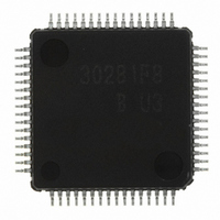
Manufacturer Part Number
M30281F8HP#U3B
Description
IC M16C/28 MCU FLASH 64K 64LQFP
Manufacturer
Renesas Electronics America
Series
M16C™ M16C/Tiny/28r
Datasheet
1.M30280F6HPU9.pdf
(425 pages)
Specifications of M30281F8HP#U3B
Core Processor
M16C/60
Core Size
16-Bit
Speed
20MHz
Connectivity
I²C, IEBus, SIO, UART/USART
Peripherals
DMA, POR, PWM, Voltage Detect, WDT
Number Of I /o
55
Program Memory Size
64KB (64K x 8)
Program Memory Type
FLASH
Ram Size
4K x 8
Voltage - Supply (vcc/vdd)
2.7 V ~ 5.5 V
Data Converters
A/D 13x10b
Oscillator Type
Internal
Operating Temperature
-40°C ~ 85°C
Package / Case
64-LQFP
For Use With
R0K330290S000BE - KIT EVAL STARTER FOR M16C/29M30290T2-CPE - EMULATOR COMPACT M16C/26A/28/29M30290T2-CPE-HP - EMULATOR COMPACT FOR M16C/TINY
Lead Free Status / RoHS Status
Lead free / RoHS Compliant
Eeprom Size
-
Available stocks
Company
Part Number
Manufacturer
Quantity
Price

Part Number:
M30281F8HP#U3BM30281F8HP#U3
Manufacturer:
Renesas Electronics America
Quantity:
10 000


M
R
R
7.1 Main Clock
e
E
1
. v
Figure 7.8 Examples of Main Clock Connection Circuit
J
6
0
The following describes the clocks generated by the clock generation circuit.
The main clock is generated by the main clock oscillation circuit. This clock is used as the clock source for
the CPU and peripheral function clocks. The main clock oscillator circuit is configured by connecting a
resonator between the X
which is disconnected from the oscillator circuit during stop mode in order to reduce the amount of power
consumed in the chip. The main clock oscillator circuit may also be configured by feeding an externally
generated clock to the X
The main clock oscillates after reset. The power consumption in the chip can be reduced by setting the
CM05 bit in the CM0 register to “1” (main clock oscillator circuit turned off) after switching the clock source
for the CPU clock to a sub clock or on-chip oscillator clock. In this case, X
because the internal feedback resistor remains on, X
During stop mode, all clocks including the main clock are turned off. Refer to 7.6 power control.
If the main clock is not used, it is recommended to connect the XIN pin to VCC to reduce power consump-
tion during reset.
C
2
9
0 .
2 /
B
0
0
8
0
4
G
J
7
a
o r
0 -
. n
(Built-in Feedback Resistor)
u
2
3
p
0
, 1
0
(
M
Microcomputer
2
0
NOTE:
1
0
6
7
1. Insert a damping resistor if required. Resistance value varies depending on the oscillator setting.
2. The external clock should not be stopped when it is connected to the X
C
Use resistance value recommended by the oscillator manufacturer. If the oscillator manufacturer
recommends that a feedback resistor be added to the chip externally, insert a feedback resistor
between X
selected as the CPU clock.
2 /
X
, 8
V
OUT
page 51
X
SS
IN
M
IN
IN
1
pin. Figure 7.8 shows the examples of main clock connection circuit.
6
IN
and X
Oscillator
C
and X
Rd
f o
2 /
(1)
8
3
) B
OUT
8
OUT
5
.
pins. The main clock oscillator circuit contains a feedback resistor,
C
C
OUT
IN
(Built-in Feedback Resistor)
IN
Microcomputer
is pulled “H” to X
X
OUT
X
IN
Open
V
V
CC
SS
IN
External Clock
pin and the main clock is
OUT
via the feedback resistor.
OUT
7. Clock Generation Circuit
goes “H”. Furthermore,
Related parts for M30281F8HP#U3B
Image
Part Number
Description
Manufacturer
Datasheet
Request
R

Part Number:
Description:
KIT STARTER FOR M16C/29
Manufacturer:
Renesas Electronics America
Datasheet:

Part Number:
Description:
KIT STARTER FOR R8C/2D
Manufacturer:
Renesas Electronics America
Datasheet:

Part Number:
Description:
R0K33062P STARTER KIT
Manufacturer:
Renesas Electronics America
Datasheet:

Part Number:
Description:
KIT STARTER FOR R8C/23 E8A
Manufacturer:
Renesas Electronics America
Datasheet:

Part Number:
Description:
KIT STARTER FOR R8C/25
Manufacturer:
Renesas Electronics America
Datasheet:

Part Number:
Description:
KIT STARTER H8S2456 SHARPE DSPLY
Manufacturer:
Renesas Electronics America
Datasheet:

Part Number:
Description:
KIT STARTER FOR R8C38C
Manufacturer:
Renesas Electronics America
Datasheet:

Part Number:
Description:
KIT STARTER FOR R8C35C
Manufacturer:
Renesas Electronics America
Datasheet:

Part Number:
Description:
KIT STARTER FOR R8CL3AC+LCD APPS
Manufacturer:
Renesas Electronics America
Datasheet:
Part Number:
Description:
KIT STARTER FOR RX610
Manufacturer:
Renesas Electronics America
Datasheet:

Part Number:
Description:
KIT STARTER FOR R32C/118
Manufacturer:
Renesas Electronics America
Datasheet:

Part Number:
Description:
KIT DEV RSK-R8C/26-29
Manufacturer:
Renesas Electronics America
Datasheet:

Part Number:
Description:
KIT STARTER FOR SH7124
Manufacturer:
Renesas Electronics America
Datasheet:

Part Number:
Description:
KIT STARTER FOR H8SX/1622
Manufacturer:
Renesas Electronics America
Datasheet:

Part Number:
Description:
KIT DEV FOR SH7203
Manufacturer:
Renesas Electronics America
Datasheet: