PIC12C672/JW Microchip Technology, PIC12C672/JW Datasheet - Page 409
PIC12C672/JW
Manufacturer Part Number
PIC12C672/JW
Description
IC MCU EPROM 2KX14 A/D 8CDIP
Manufacturer
Microchip Technology
Series
PIC® 12Cr
Datasheets
1.PIC16F688T-ISL.pdf
(688 pages)
2.PIC12CE673-10P.pdf
(129 pages)
3.PIC12CE673-10P.pdf
(14 pages)
Specifications of PIC12C672/JW
Core Processor
PIC
Core Size
8-Bit
Speed
10MHz
Peripherals
POR, WDT
Number Of I /o
5
Program Memory Size
3.5KB (2K x 14)
Program Memory Type
EPROM, UV
Ram Size
128 x 8
Voltage - Supply (vcc/vdd)
3 V ~ 5.5 V
Data Converters
A/D 4x8b
Oscillator Type
Internal
Operating Temperature
0°C ~ 70°C
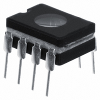
Package / Case
8-CDIP (0.300", 7.62mm) Window
Lead Free Status / RoHS Status
Contains lead / RoHS non-compliant
Eeprom Size
-
Connectivity
-
Other names
Q395827
Available stocks
Company
Part Number
Manufacturer
Quantity
Price
Company:

Part Number:
PIC12C672/JW
Manufacturer:
MICKO
Quantity:
2 100


1997 Microchip Technology Inc.
Legend C
VA
Rs
V
I
R
SS
C
LEAKAGE
PIN
T
IC
HOLD
Section 22. Basic 8-bit A/D Converter
RAx
Figure 22-3:
C
5 pF
PIN
Note 1: The reference voltage (V
Note 2: The charge holding capacitor (C
Note 3: The maximum recommended impedance for analog sources is 10 k . This is
Note 4: After a conversion has completed, a 2.0 T
= input capacitance
= threshold voltage
= leakage current at the pin due to
= interconnect resistance
= sampling switch
= sample/hold capacitance (from DAC)
VARIOUS JUNCTIONS
out.
required to meet the pin leakage specification.
can begin again. During this time the holding capacitor is not connected to the
selected A/D input channel.
Analog Input Model
V
DD
V
V
T
T
= 0.6V
= 0.6V
REF
I leakage
500 nA
) has no effect on the equation, since it cancels itself
R
IC
HOLD
1k
) is not discharged after each conversion.
V
SS
DD
AD
Sampling
Switch
delay must complete before acquisition
6V
5V
4V
3V
2V
R
SS
Sampling Switch
5 6 7 8 9 10 11
V
SS
C
( k )
HOLD
= 51.2 pF
DS31022A-page 22-7
22
Related parts for PIC12C672/JW
Image
Part Number
Description
Manufacturer
Datasheet
Request
R

Part Number:
Description:
8-Pin/ 8-Bit CMOS Microcontroller with EEPROM Data Memory
Manufacturer:
Microchip Technology
Part Number:
Description:
IC, 8BIT MCU, PIC12, 32MHZ, DFN-8
Manufacturer:
Microchip Technology
Datasheet:
Part Number:
Description:
IC, 8BIT MCU, PIC12, 32MHZ, DFN-8
Manufacturer:
Microchip Technology
Datasheet:

Part Number:
Description:
Manufacturer:
Microchip Technology Inc.
Datasheet:
Part Number:
Description:
Manufacturer:
Microchip Technology Inc.
Datasheet:
Part Number:
Description:
Manufacturer:
Microchip Technology Inc.
Datasheet:
Part Number:
Description:
Manufacturer:
Microchip Technology Inc.
Datasheet:
Part Number:
Description:
Manufacturer:
Microchip Technology Inc.
Datasheet:
Part Number:
Description:
Manufacturer:
Microchip Technology Inc.
Datasheet:
Part Number:
Description:
Manufacturer:
Microchip Technology Inc.
Datasheet: