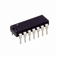
ACE1502VN14 Fairchild Semiconductor, ACE1502VN14 Datasheet - Page 20

ACE1502VN14
Manufacturer Part Number
ACE1502VN14
Description
IC MCU 2KBIT EEPROM HBC 14DIP
Manufacturer
Fairchild Semiconductor
Series
ACEX® 15xxr
Datasheet
1.ACE1502EN14.pdf
(33 pages)
Specifications of ACE1502VN14
Core Processor
ACE1502
Core Size
8-Bit
Speed
25MHz
Peripherals
Brown-out Detect/Reset, LVD, POR, PWM, WDT
Number Of I /o
8
Program Memory Size
2KB (2K x 8)
Program Memory Type
EEPROM
Eeprom Size
64 x 8
Ram Size
64 x 8
Voltage - Supply (vcc/vdd)
1.8 V ~ 3.6 V
Oscillator Type
Internal
Operating Temperature
-40°C ~ 125°C
Package / Case
14-DIP (0.300", 7.62mm)
Lead Free Status / RoHS Status
Lead free / RoHS Compliant
Data Converters
-
Connectivity
-
Other names
ACE1502VN14_NL
ACE1502VN14_NL
ACE1502VN14_NL
ACE1502 Product Family Rev. 1.7
Figure 22. Bit Period Configuration (BPSEL) Register
Figure 23. HBC Control (HBCNTRL) Register
Figure 24. HBC signals for one byte message in PWM format
Figure 25. Sending series of encoded messages
OCFLAG
START/STOP
START/STOP
Bit 7
Bit 7
0
OCFLAG
TXBUSY
ShiftCLK
CLOCK
Output
OCFLAG
G2/G5
TXBUSY
Condition:
BPSEL = 0x12 [ "1", " 0 " = 3 * IR/RF Clocks]
DAT0 = 0x52
No. bit to encode = 8 (HBCNTRL = XXXX0111b)
DAT0
IR/RF
CLOCK
Bit 7
ShiftCLK
Output
G2/G5
Conditions:
BPSEL = 0x12 [ "1", " 0 " = 3 * IR/RF Clocks]
DAT0 = 0x52 , 0x92
No. bit to encode = 8 (HBCNTRL = XXXX0111b)
DAT0
IR/RF
Bit 7
IOSEL
Bit 6
Bit 6
"0"
0
"0"
"0"
"1"
START / STOP
Bit 5
Bit 5
"0"
"0"
"1" "0"
"1"
BPL[2:0]
"0"
TXBUSY
Bit 4
Bit 4
"1"
"0"
"0"
20
"1"
Software must set the START bit while OCFLAG is set in
order to send another message without introducing a delay.
Bit 3
Bit 3
"1"
"0"
0
"0"
"1"
"0"
Bit 2
Bit 2
"0"
"0"
"0"
"1"
FRAME[2:0]
BPH[2:0]
Bit 1
Bit 1
"0"
"1"
STOP bit clear,
transmission ends.
www.fairchildsemi.com
"0"
Bit 0
Bit 0


