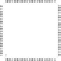
LH75411N0Q100C0 Sharp Microelectronics, LH75411N0Q100C0 Datasheet - Page 82

LH75411N0Q100C0
Manufacturer Part Number
LH75411N0Q100C0
Description
IC ARM7 BLUESTREAK MCU 144LQFP
Manufacturer
Sharp Microelectronics
Series
BlueStreak ; LH7r
Specifications of LH75411N0Q100C0
Core Processor
ARM7
Core Size
16/32-Bit
Speed
84MHz
Connectivity
EBI/EMI, SPI, SSI, SSP, UART/USART
Peripherals
Brown-out Detect/Reset, DMA, LCD, POR, PWM, WDT
Number Of I /o
76
Program Memory Type
ROMless
Ram Size
32K x 8
Voltage - Supply (vcc/vdd)
1.7 V ~ 3.6 V
Data Converters
A/D 8x10b
Oscillator Type
Internal
Operating Temperature
-40°C ~ 85°C
Package / Case
144-LQFP
Data Bus Width
32 bit
Data Ram Size
32 KB
Maximum Clock Frequency
84 MHz
Number Of Programmable I/os
8
Operating Supply Voltage
3 V to 3.6 V
Maximum Operating Temperature
+ 85 C
Mounting Style
SMD/SMT
Minimum Operating Temperature
- 40 C
Lead Free Status / RoHS Status
Lead free / RoHS Compliant
Eeprom Size
-
Program Memory Size
-
Lead Free Status / Rohs Status
Details
Available stocks
Company
Part Number
Manufacturer
Quantity
Price
Company:
Part Number:
LH75411N0Q100C0
Manufacturer:
Sharp Microelectronics
Quantity:
10 000
Company:
Part Number:
LH75411N0Q100C0,55
Manufacturer:
NXP Semiconductors
Quantity:
10 000
LH75400/01/10/11
CONTENT REVISIONS
content, causing it to differ from previous versions.
82
05-20-05
03-30-06
5-14-04
This document contains the following changes to
DATE
18 - 20,
28 - 30,
70 – 72 Figures 18 – 19
70 – 76 Figures 20 – 25
12, 22,
10, 20,
30, 40,
PAGE
8 - 10,
69, 70
67,68
NO.
—
49
46
58
61
62
64
73
—
59
51
72
—
57
58
62
62
63
1
1
1
1
Page Note
Tables 1, 3, 5, 7
AD-TFT, HR-TFT
Interface description
Table 22
Table 23
Table 27
Current
Consumption
Figures 18, 19
Table Notes
Table Notes
Table 24
Figure 20
Features
Pin Drawings
Table 21
Very Low
Temperatures and
Noise Immunity
Power Supply
Sequencing
Linear Regulator
Figures 15,16
Clock Sources
Figure 11
Figure 21
SSP Features
Table 28
PARAGRAPH OR
ILLUSTRATION
—
—
—
‘Preliminary’ Status removed.
Core Speed Specification and Crystal Specifications updated.
Tolerance of XTAL inputs noted.
Column heading for Reset behavior clarified; memory interface lines behavior dur-
ing Reset clarified; notes added regarding voltage tolerance of XTAL inputs, need
for 10 kΩ pull-up resistor to activate the on-chip linear regulator; SSPFRM and
SSPCLK signals type corrected to Output.
Corrected to Advanced LCD Interface description, text updated for clarity.
Rewritten to reflect updated specifications
DC Characteristics of XTAL inputs added.
Pull-up resistor for Linear Regulator specified.
Start-up Characteristics Table expanded.
Current Consumption by Operating Mode added.
Start-up Characteristics Figure expanded.
Suggested External Components added.
Recommended PCB Footprint added.
Version number rolled to 1.1.
Pull-up resistor value for Linear Regulator updated.
Text regarding interrupt-driven transfers clarified.
Specification Drawing updated to add clearance under chip.
Version number rolled to 1.2.
Top Speed adjusted to reflect MAX. Temp and MIN. Voltage
Note added to refer to device Pin 1 marking for proper orientation.
Footnote added regarding power sequencing.
MAX specification for Crystal Frequency changed to 20 MHz; Note 3 clarified.
Text regarding operating the device at very low temperatures with an external
clock. added.
Specifications for power supply sequencing added.
Note about using the Linear Regulator to power external devices added.
Clarified tIDD for more than one WAIT state, added MAX. value for tOHWE.
Added data latch point for Memory Read cycles.
Moved DMA timing waveforms into the Data Sheet for ease of maintenance and
to keep all interface diagrams together in one place.
Moved LCD timing waveforms into the Data Sheet for ease of maintenance and to
keep all interface diagrams together in one place.
Table 31. Record of Revisions
Version 1.2
SUMMARY OF CHANGES
System-on-Chip
Data Sheet


