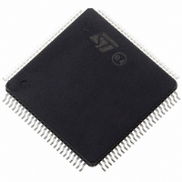
STR735FZ1T7 STMicroelectronics, STR735FZ1T7 Datasheet - Page 29

STR735FZ1T7
Manufacturer Part Number
STR735FZ1T7
Description
IC MCU ARM7 128K FLASH 144-TQFP
Manufacturer
STMicroelectronics
Series
STR7r
Datasheet
1.STR735FZ2T7.pdf
(52 pages)
Specifications of STR735FZ1T7
Core Processor
ARM7
Core Size
32-Bit
Speed
36MHz
Connectivity
I²C, SPI, UART/USART
Peripherals
DMA, POR, PWM, WDT
Number Of I /o
112
Program Memory Size
128KB (128K x 8)
Program Memory Type
FLASH
Ram Size
16K x 8
Voltage - Supply (vcc/vdd)
4.5 V ~ 5.5 V
Data Converters
A/D 16x10b
Oscillator Type
Internal
Operating Temperature
-40°C ~ 105°C
Package / Case
144-TQFP, 144-VQFP
Processor Series
STR735x
Core
ARM7TDMI
Data Bus Width
32 bit
Data Ram Size
16 KB
Interface Type
I2C, SPI, UART
Maximum Clock Frequency
36 MHz
Number Of Programmable I/os
112
Number Of Timers
13
Maximum Operating Temperature
+ 105 C
Mounting Style
SMD/SMT
3rd Party Development Tools
EWARM, EWARM-BL, MCBSTR730, MDK-ARM, RL-ARM, ULINK2
Development Tools By Supplier
STR730-SK/HIT, STR730-SK/IAR, STR730-SK/RAIS, STR731-SK/IAR, STR730-EVAL, STX-PRO/RAIS, STX-RLINK, STR79-RVDK/CPP, STR79-RVDK, STR79-RVDK/UPG
Minimum Operating Temperature
- 40 C
On-chip Adc
10 bit, 16 Channel
Lead Free Status / RoHS Status
Lead free / RoHS Compliant
Eeprom Size
-
Lead Free Status / Rohs Status
Details
Other names
497-5143-2
Available stocks
Company
Part Number
Manufacturer
Quantity
Price
Company:
Part Number:
STR735FZ1T7
Manufacturer:
STMicroelectronics
Quantity:
10 000
STR73xFxx
4.3.2
Note:
1
2
Clock and timing characteristics
Crystal / ceramic resonator oscillator
The STR73xF can operate with a crystal oscillator or resonator clock source.
simple model of the internal oscillator driver as well as example of connection for an oscillator or a
resonator.
Figure 12. Crystal oscillator and resonator
XTAL2 must not be used to directly drive external circuits.
For test or boot purpose, XTAL2 can be used as an high impedance input pin to provide an
external clock to the device. XTAL1 should be grounded, and XTAL2 connected to a wave
signal generator providing a 0 to VDD signal. Directly driving XTAL2 may results in
deteriorated jitter and duty cycle.
C
L
STR73x
Crystal
R
S
STR73x
C
L
R
F
I
V
DD
Resonator
STR73x
Electrical parameters
Figure 12
describes a
29/52


