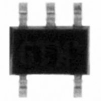
TSV631ICT STMicroelectronics, TSV631ICT Datasheet - Page 13

TSV631ICT
Manufacturer Part Number
TSV631ICT
Description
IC OPAMP RRIO SGL LV LP SC70-5
Manufacturer
STMicroelectronics
Datasheet
1.TSV631ILT.pdf
(23 pages)
Specifications of TSV631ICT
Amplifier Type
General Purpose
Number Of Circuits
1
Output Type
Rail-to-Rail
Slew Rate
0.34 V/µs
Gain Bandwidth Product
880kHz
Current - Input Bias
1pA
Voltage - Input Offset
3000µV
Current - Supply
60µA
Current - Output / Channel
74mA
Voltage - Supply, Single/dual (±)
1.5 V ~ 5.5 V
Operating Temperature
-40°C ~ 125°C
Mounting Type
Surface Mount
Package / Case
SC-70-5, SC-88A, SOT-323-5, SOT-353, 5-TSSOP
Number Of Channels
1
Voltage Gain Db
98 dB
Common Mode Rejection Ratio (min)
60 dB
Input Offset Voltage
3 mV
Operating Supply Voltage
3 V, 5 V
Supply Current
60 uA
Maximum Operating Temperature
+ 125 C
Mounting Style
SMD/SMT
Minimum Operating Temperature
- 40 C
Lead Free Status / RoHS Status
Lead free / RoHS Compliant
-3db Bandwidth
-
Lead Free Status / Rohs Status
Details
Other names
497-8543-2
Available stocks
Company
Part Number
Manufacturer
Quantity
Price
Part Number:
TSV631ICT
Manufacturer:
ST
Quantity:
20 000
TSV630, TSV630A, TSV631, TSV631A
3.5
3.6
3.7
Optimization of DC and AC parameters
These devices use an innovative approach to reduce the spread of the main DC and AC
parameters. An internal adjustment achieves a very narrow spread of the current
consumption (60 µA typical, min/max at
consumption value, such as GBP, SR and AVd, benefit from this narrow dispersion. All parts
present a similar speed and the same behavior in terms of stability. In addition, the minimum
values of GBP and SR are guaranteed (GBP = 730 kHz minimum and SR = 0.25 V/µs
minimum).
Driving resistive and capacitive loads
These products are micro-power, low-voltage operational amplifiers optimized to drive rather
large resistive loads, above 2 kΩ . For lower resistive loads, the THD level may significantly
increase.
In a follower configuration, these operational amplifiers can drive capacitive loads up to
100 pF with no oscillations. When driving larger capacitive loads, adding an in-series
resistor at the output can improve the stability of the devices (see
recommended in-series resistor values). Once the in-series resistor value has been
selected, the stability of the circuit should be tested on bench and simulated with the
simulation model.
Figure 22. In-series resistor vs. capacitive load
PCB layouts
For correct operation, it is advised to add 10 nF decoupling capacitors as close as possible
to the power supply pins.
Doc ID 15242 Rev 2
±17 %).
Parameters linked to the current
Figure 22
Application information
for
13/23


