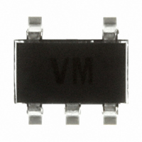
TSV991AILT STMicroelectronics, TSV991AILT Datasheet - Page 10

TSV991AILT
Manufacturer Part Number
TSV991AILT
Description
IC OPAMP R-R SGL 20MHZ SOT23-5
Manufacturer
STMicroelectronics
Datasheet
1.TSV992AIDT.pdf
(20 pages)
Specifications of TSV991AILT
Amplifier Type
General Purpose
Number Of Circuits
1
Output Type
Rail-to-Rail
Slew Rate
10 V/µs
Gain Bandwidth Product
20MHz
Current - Input Bias
1pA
Current - Supply
820µA
Current - Output / Channel
35mA
Voltage - Supply, Single/dual (±)
2.5 V ~ 5.5 V
Operating Temperature
-40°C ~ 125°C
Mounting Type
Surface Mount
Package / Case
SOT-23-5, SC-74A, SOT-25
Number Of Channels
1
Voltage Gain Db
91 dB
Common Mode Rejection Ratio (min)
62 dB
Input Offset Voltage
1.5 mV
Operating Supply Voltage
3 V, 5 V
Supply Current
1.1 mA
Maximum Operating Temperature
+ 125 C
Mounting Style
SMD/SMT
Minimum Operating Temperature
- 40 C
Lead Free Status / RoHS Status
Lead free / RoHS Compliant
-3db Bandwidth
-
Voltage - Input Offset
-
Lead Free Status / Rohs Status
Details
Other names
497-5833-2
Available stocks
Company
Part Number
Manufacturer
Quantity
Price
Company:
Part Number:
TSV991AILT
Manufacturer:
STMicroelectronics
Quantity:
2 400
Part Number:
TSV991AILT
Manufacturer:
ST
Quantity:
20 000
Application information
3
3.1
3.2
10/20
Figure 15. In-series resistor vs. capacitive
Application information
Driving resistive and capacitive loads
These products are low-voltage, low-power operational amplifiers optimized to drive rather
large resistive loads above 2 kΩ .
The TSV99x are not unity gain stable. To ensure proper stability they must be used in a gain
configuration, with a minimum gain of -3 or +4.
However, they can be used in a follower configuration by adding a small in-series resistor at
the output, which drastically improves the stability of the device
recommended in-series resistor values). Once the in-series resistor value has been
selected, the stability of the circuit should be tested on bench and simulated with the
simulation model.
Another way to improve stability and reduce peaking is to add a capacitor in parallel with the
feedback resistor. As shown in
peaking versus capacitive load (inverting gain configuration, gain = -2).
PCB layouts
For correct operation, it is advised to add 10 nF decoupling capacitors as close as possible
to the power supply pins.
load when TSV99x used in follower
configuration
Doc ID 12833 Rev 8
Figure
16, the feedback capacitor drastically reduces the
Figure 16. Peaking versus capacitive load,
with or without feedback capacitor
in inverting gain configuration
(Figure 15
TSV99x-TSV99xA
shows the


