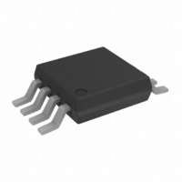
AD8275BRMZ Analog Devices Inc, AD8275BRMZ Datasheet - Page 12

AD8275BRMZ
Manufacturer Part Number
AD8275BRMZ
Description
IC AMP DIFF R-R LDRIFT 8MSOP
Manufacturer
Analog Devices Inc
Datasheet
1.AD8275BRMZ-R7.pdf
(16 pages)
Specifications of AD8275BRMZ
Amplifier Type
Differential
Number Of Circuits
1
Output Type
Rail-to-Rail
Slew Rate
25 V/µs
-3db Bandwidth
15MHz
Voltage - Input Offset
150µV
Current - Supply
1.9mA
Current - Output / Channel
30mA
Voltage - Supply, Single/dual (±)
3.3 V ~ 15 V
Operating Temperature
-40°C ~ 85°C
Mounting Type
Surface Mount
Package / Case
8-MSOP, Micro8™, 8-uMAX, 8-uSOP,
No. Of Amplifiers
1
Input Offset Voltage
500µV
Bandwidth
15MHz
Supply Voltage Range
3.3V To 15V
Supply Current
1.9mA
Amplifier Case Style
MSOP
No. Of Pins
8
Rohs Compliant
Yes
Lead Free Status / RoHS Status
Lead free / RoHS Compliant
Gain Bandwidth Product
-
Current - Input Bias
-
Available stocks
Company
Part Number
Manufacturer
Quantity
Price
Part Number:
AD8275BRMZ
Manufacturer:
ADI/亚德诺
Quantity:
20 000
Company:
Part Number:
AD8275BRMZ-R7
Manufacturer:
Analog Devices Inc
Quantity:
1 793
Company:
Part Number:
AD8275BRMZ-R7
Manufacturer:
LT
Quantity:
2 346
AD8275
POWER SUPPLIES
Use a stable dc voltage to power the AD8275. Noise on the
supply pins can adversely affect performance. Place a bypass
capacitor of 0.1 µF between each supply pin and ground, as
close to each pin as possible. A tantalum capacitor of 10 µF
should also be used between each supply and ground. It can
be farther away from the AD8275 and typically can be shared
by other precision integrated circuits.
REFERENCE
The reference terminals are used to provide a bias level for the
output. For example, in a single-supply 5 V operation, the
reference terminals can be set so that the output is biased at
2.5 V. This ensures that the output can swing positive or
negative around a 2.5 V level.
Figure 33 and Figure 34 illustrate two different ways to set the
reference voltage. See the Basic Connection section for the
differences between the two settings.
The allowable reference voltage range is a function of the
common-mode input and supply voltages. The REF1 and REF2
pins should not exceed either +V
The REFx terminals should be driven by low source impedance
because parasitic resistance in series with REF1 and REF2 can
adversely affect CMRR and gain accuracy.
2
3
3
2
3
+IN
AD8275
+IN
AD8275
–IN
–IN
50kΩ
50kΩ
50kΩ
50kΩ
CORRECT
+V
+V
7
4
7
4
–V
–V
10kΩ
10kΩ
S
S
20kΩ
20kΩ
20kΩ
20kΩ
S
S
Figure 35. REF1 and REF2 Pin Guidelines
SENSE
SENSE
REF2
REF1
REF2
REF1
OUT
OUT
5
6
8
1
5
6
8
1
V
V
REF
REF
S
2
2
3
2
2
3
or −V
–IN
+IN
+IN
AD8275
–IN
+IN
+IN
AD8275
IN
IN
50kΩ
50
50kΩ
50
50kΩ
50kΩ
0kΩ
0kΩ
INCORRECT
S
by more than 0.5 V.
+V
+V
7
4
4
7
–V
–V
10kΩ
10kΩ
S
20kΩ REF2
20kΩ
S
20kΩ REF2
20kΩ
0kΩ R
0kΩ R
S
S
SENSE
SENSE
REF1
REF1
REF1
REF1
OUT
O
OUT
NSE
NSE
5
5
6
8
1
1
5
5
6
8
1
1
V
V
REF
REF
Rev. A | Page 12 of 16
COMMON-MODE INPUT VOLTAGE RANGE
The common-mode voltage range is a function of the input
voltage range of the internal op amp, the supply voltage, and
the reference voltage.
Equation 1 expresses the maximum positive common-mode
voltage range.
V
Equation 2 expresses the minimum common-mode voltage
range.
The voltage range of the internal op amp varies depending on
temperature. The equations reflect a typical input voltage range
of +V
expected common-mode ranges for typical configurations.
Table 5. Expected Common-Mode Voltage Range for Typical
Configurations
+V
5
5
5
3.3
3.3
5
5
5
5
5
5
5
1
INPUT PROTECTION
The inputs of the AD8275, +IN and −IN, are protected by ESD
diodes that clamp 40 V above −V
operating on a single +5 V supply, the ESD diode conducts at
input voltages less than −35 V and greater than +40 V.
If the input voltage is expected to exceed the maximum ratings
of the AD8275, use external transorbs. Adding series resistors to
the inputs of the AD8275 is not recommended because the
internal resistor ratios are matched to provide optimal CMRR
and gain accuracy. Adding external series resistors to the input
degrades the performance of the AD8275.
All other pins are protected by ESD diodes that clamp 0.5 V
beyond either supply rail. For example, the voltage range of the
REF1 and REF2 pins on a 5 V supply is −0.5 V to +5.5 V.
–V
CM_POS
S
S
(V)
= 0 V.
V
S
CM_NEG
− 0.9 V and −V
≤ 13.14(+V
1
V
5
2.5
4.096
3.3
2.5
5
4.096
3
2.5
2.048
1.25
0
≥ 6(–V
REF1
(V)
S
) – 7.14(–V
S
) – 5((REF1 + REF2)/2) – 0.11
S
+ 1.35 V over temperature. Table 5 lists
V
0
0
0
0
0
5
4.096
3
2.5
2.048
1.25
0
REF2
S
) – 5((REF1 + REF2)/2) – 29.69 (1)
(V)
S
and 40 V below +V
V
23.5
29.8
25.8
5.4
7.4
11.0
15.5
21.0
23.5
25.8
29.8
36.0
CM
+ (V)
S
. When
V
−12.6
−6.4
−10.4
−8.4
−6.4
−25.1
−20.6
−15.1
−12.6
−10.4
−6.4
−0.1
CM
− (V)
(2)


