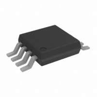
AD8275BRMZ Analog Devices Inc, AD8275BRMZ Datasheet - Page 14

AD8275BRMZ
Manufacturer Part Number
AD8275BRMZ
Description
IC AMP DIFF R-R LDRIFT 8MSOP
Manufacturer
Analog Devices Inc
Datasheet
1.AD8275BRMZ-R7.pdf
(16 pages)
Specifications of AD8275BRMZ
Amplifier Type
Differential
Number Of Circuits
1
Output Type
Rail-to-Rail
Slew Rate
25 V/µs
-3db Bandwidth
15MHz
Voltage - Input Offset
150µV
Current - Supply
1.9mA
Current - Output / Channel
30mA
Voltage - Supply, Single/dual (±)
3.3 V ~ 15 V
Operating Temperature
-40°C ~ 85°C
Mounting Type
Surface Mount
Package / Case
8-MSOP, Micro8™, 8-uMAX, 8-uSOP,
No. Of Amplifiers
1
Input Offset Voltage
500µV
Bandwidth
15MHz
Supply Voltage Range
3.3V To 15V
Supply Current
1.9mA
Amplifier Case Style
MSOP
No. Of Pins
8
Rohs Compliant
Yes
Lead Free Status / RoHS Status
Lead free / RoHS Compliant
Gain Bandwidth Product
-
Current - Input Bias
-
Available stocks
Company
Part Number
Manufacturer
Quantity
Price
Part Number:
AD8275BRMZ
Manufacturer:
ADI/亚德诺
Quantity:
20 000
Company:
Part Number:
AD8275BRMZ-R7
Manufacturer:
Analog Devices Inc
Quantity:
1 793
Company:
Part Number:
AD8275BRMZ-R7
Manufacturer:
LT
Quantity:
2 346
AD8275
APPLICATIONS INFORMATION
DRIVING A SINGLE-ENDED ADC
The AD8275 provides the common-mode rejection that SAR
ADCs often lack. In addition, it enables designers to use cost-
effective, precision, 16-bit ADCs such as the AD7685, yet still
condition ±10 V signals.
One important factor in selecting an ADC driver is its ability to
settle within the acquisition window of the ADC. The AD8275
is able to drive medium speed SAR ADCs.
In Figure 38, the 2.7 nF capacitor serves to store and deliver
necessary charge to the switched capacitor input of the ADC.
The 33 Ω series resistor reduces the burden of the 2.7 nF load
from the amplifier and isolates it from the kickback current
injected from the switched capacitor input of the AD7685. The
output impedance of the amplifier can affect the THD of the
ADC. In this case, the combined impedance of the 33 Ω resistor
and the output impedance of the AD8275 provides extremely
low THD of −112 dB. Figure 39 shows the ac response of the
AD8275 driving the AD7685.
VIN
2
3
–IN
+IN
AD8275
50kΩ
50kΩ
+5V
Figure 38. Driving a Single-Ended ADC
+V
–V
7
4
S
S
10kΩ
20kΩ
20kΩ
SENSE
+10V
–10V
REF2
REF1
OUT
0.1µF
5
6
8
1
Figure 40. AD8275 Configured for Differential Output (for Driving a Differential ADC)
2.7nF
33Ω
VREF
(ADR444,
ADR445)
2
3
–IN
+IN
AD8275
50kΩ
50kΩ
0.1µF
+5V
IN+
IN–
+V
–V
REF
7
4
AD7685
S
10kΩ
S
20kΩ
20kΩ
10µF
SENSE
VDD
GND
REF2
REF1
OUT
0.1µF
Rev. A | Page 14 of 16
5
6
8
1
2kΩ
2kΩ
The AD8275 can condition signals for higher resolution ADCs
such as 18-bit SAR converters, provided that a narrower
bandwidth is sampled to limit noise.
DIFFERENTIAL OUTPUTS
In certain applications, it is necessary to create a differential signal.
For example, high resolution ADCs often require a differential
input. In other cases, transmission over a long distance can require
differential signals for better immunity to interference.
Figure 40 shows how to configure the AD8275 to output a
differential signal. The
topology to create a differential voltage. VREF sets the output
midpoint. Errors from the op amp are common to both outputs
and are thus common mode. Likewise, errors from using
mismatched resistors cause a common-mode dc offset error.
Such errors are rejected in differential signal processing by
differential input ADCs or by instrumentation amplifiers.
When using this circuit to drive a differential ADC, V
set using a resistor divider from the ADC reference to make the
output ratiometric with the ADC.
Reference of the Evaluation Board (Input = 20 V p-p, 1 kHz, THD = −112 dB)
Figure 39. FFT of AD8275 Directly Driving the AD7685 Using the 5 V
8.2µF
–100
–110
–120
–130
–140
–150
–160
–170
–10
–20
–30
–40
–50
–60
–70
–80
–90
10
0
AD8655
0
1
+V
V
–V
REF
+5V
0.1µF
OUT
OUT
2
= 2.5V
AD8655
+3.5V
+2.5V
+1.5V
+3.5V
+2.5V
+1.5V
3
FREQUENCY (kHz)
4
op amp is used in an inverting
5
6
7
8
9
REF
can be
10


