EL5420CRZ-T7 Intersil, EL5420CRZ-T7 Datasheet - Page 17
EL5420CRZ-T7
Manufacturer Part Number
EL5420CRZ-T7
Description
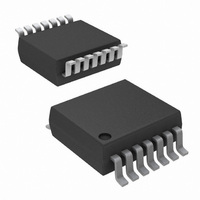
IC OPAMP QUAD R-R 12MHZ 14-TSSOP
Manufacturer
Intersil
Datasheet
1.EL5220CYZ.pdf
(20 pages)
Specifications of EL5420CRZ-T7
Amplifier Type
Voltage Feedback
Number Of Circuits
4
Output Type
Rail-to-Rail
Slew Rate
10 V/µs
Gain Bandwidth Product
8MHz
-3db Bandwidth
12MHz
Current - Input Bias
2nA
Voltage - Input Offset
2000µV
Current - Supply
500µA
Current - Output / Channel
30mA
Voltage - Supply, Single/dual (±)
4.5 V ~ 16.5 V, ±2.25 V ~ 8.25 V
Operating Temperature
-40°C ~ 85°C
Mounting Type
Surface Mount
Package / Case
14-TSSOP
Lead Free Status / RoHS Status
Lead free / RoHS Compliant


Thin Shrink Small Outline Package Family (TSSOP)
C
SEATING
PLANE
N LEADS
E
0.10 C
A
0.25
E1
B
c
A2
M
e
N
1
C A B
A1
SEE DETAIL ‚Äö
TOP VIEW
b
DETAIL X
SIDE VIEW
D
END VIEW
17
L1
(N/2)+1
L
(N/2)
0.10
M
0¬¨¬®Ðê
0.05
PIN #1 I.D.
C A B
2X
N/2 LEAD TIPS
A
GAUGE
PLANE
0.20 C
EL5120, EL5220, EL5420
0.25
B A
H
MDP0044
THIN SHRINK SMALL OUTLINE PACKAGE FAMILY
NOTES:
SYMBOL
1. Dimension “D” does not include mold flash, protrusions or gate
2. Dimension “E1” does not include interlead flash or protrusions.
3. Dimensions “D” and “E1” are measured at dAtum Plane H.
4. Dimensioning and tolerancing per ASME Y14.5M-1994.
A1
A2
E1
L1
D
A
b
E
e
L
c
burrs. Mold flash, protrusions or gate burrs shall not exceed
0.15mm per side.
Interlead flash and protrusions shall not exceed 0.25mm per
side.
14 LD 16 LD 20 LD 24 LD 28 LD
1.20
0.10
0.90
0.25
0.15
5.00
6.40
4.40
0.65
0.60
1.00
1.20
0.10
0.90
0.25
0.15
5.00
6.40
4.40
0.65
0.60
1.00
MILLIMETERS
1.20
0.10
0.90
0.25
0.15
6.50
6.40
4.40
0.65
0.60
1.00
1.20
0.10
0.90
0.25
0.15
7.80
6.40
4.40
0.65
0.60
1.00
1.20
0.10
0.90
0.25
0.15
9.70
6.40
4.40
0.65
0.60
1.00
TOLERANCE
+0.05/-0.06
+0.05/-0.06
Reference
Rev. F 2/07
March 4, 2009
±0.05
±0.05
±0.10
±0.10
±0.15
Basic
Basic
Max
FN7186.6
Related parts for EL5420CRZ-T7
Image
Part Number
Description
Manufacturer
Datasheet
Request
R

Part Number:
Description:
IC OPAMP QUAD R-R 12MHZ 14-TSSOP
Manufacturer:
Intersil
Datasheet:
Part Number:
Description:
IC OPAMP QUAD R-R 12MHZ 14-TSSOP
Manufacturer:
Intersil
Datasheet:
Part Number:
Description:
IC OPAMP QUAD R-R 12MHZ 14-TSSOP
Manufacturer:
Intersil
Datasheet:

Part Number:
Description:
Intersil Corporation [CMOS Serial Controller Interface]
Manufacturer:
Intersil Corporation
Datasheet:
Part Number:
Description:
Manufacturer:
Intersil Corporation
Datasheet:
Part Number:
Description:
357-036-542-201 CARDEDGE 36POS DL .156 BLK LOPRO
Manufacturer:
Intersil Corporation
Datasheet:
Part Number:
Description:
1024-Word x 4-Bit LSI Static RAM
Manufacturer:
Intersil Corporation
Datasheet:
Part Number:
Description:
General Purpose NPN Transistor Arrays FN341.4
Manufacturer:
Intersil Corporation
Datasheet:
Part Number:
Description:
CMOS 16-Bit Microprocessor
Manufacturer:
Intersil Corporation
Datasheet:
Part Number:
Description:
Manufacturer:
Intersil Corporation
Datasheet:
Part Number:
Description:
Manufacturer:
Intersil Corporation
Datasheet:
Part Number:
Description:
Manufacturer:
Intersil Corporation
Datasheet:
Part Number:
Description:
Manufacturer:
Intersil Corporation
Datasheet:
Part Number:
Description:
CMOS 6-Bit Latch and Decoder Memory Interfaces
Manufacturer:
Intersil Corporation
Datasheet:
Part Number:
Description:
CA3046General Purpose NPN Transistor Arrays
Manufacturer:
Intersil Corporation
Datasheet: