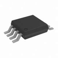
OP2177ARM-R2 Analog Devices Inc, OP2177ARM-R2 Datasheet - Page 10

OP2177ARM-R2
Manufacturer Part Number
OP2177ARM-R2
Description
IC OPAMP GP 1.3MHZ DUAL LN 8MSOP
Manufacturer
Analog Devices Inc
Datasheet
1.OP2177ARZ.pdf
(24 pages)
Specifications of OP2177ARM-R2
Rohs Status
RoHS non-compliant
Design Resources
16-Bit Fully Isolated Voltage Output Module Using AD5662, ADuM1401, and External Amplifiers (CN0063)
Amplifier Type
General Purpose
Number Of Circuits
2
Slew Rate
0.7 V/µs
Gain Bandwidth Product
1.3MHz
Current - Input Bias
500pA
Voltage - Input Offset
15µV
Current - Supply
400µA
Current - Output / Channel
10mA
Voltage - Supply, Single/dual (±)
5 V ~ 36 V, ±2.5 V ~ 18 V
Operating Temperature
-40°C ~ 125°C
Mounting Type
Surface Mount
Package / Case
8-MSOP, Micro8™, 8-uMAX, 8-uSOP,
Output Type
-
-3db Bandwidth
-
Other names
OP2177ARM-R2
OP2177ARM-R2TR
OP2177ARM-R2TR
OP1177/OP2177/OP4177
–10
–20
120
100
–20
–40
–60
–80
60
50
40
30
20
10
100k
80
60
40
20
1.4
1.2
1.0
0.8
0.6
0.4
0.2
0
0
0.001
0
1k
Figure 32. Open-Loop Gain and Phase Shift vs. Frequency
Figure 31. Output Voltage to Supply Rail vs. Load Current
A
A
A
V
T
V
V
V
A
SY
GAIN
= 100
= 10
= 1
= 25°C
= ±5V
Figure 33. Closed-Loop Gain vs. Frequency
10k
0.01
SINK
SOURCE
FREQUENCY (Hz)
FREQUENCY (Hz)
100k
LOAD CURRENT (mA)
1M
0.1
1M
PHASE
1
V
V
C
R
10M
SY
IN
L
L
V
C
R
SY
L
L
= 0
=
= 4mV p-p
= ±5V
= 0
=
∞
= ±5V
∞
10M
100M
10
270
225
180
135
90
45
0
–45
–90
Rev. G | Page 10 of 24
GND
GND
500
450
400
350
300
250
200
150
100
50
0
100
V
C
R
V
A
V
V
SY
IN
L
L
V
SY
IN
Figure 34. Output Impedance vs. Frequency
= 300pF
= 2kΩ
= 1
Figure 35. Large Signal Transient Response
Figure 36. Small Signal Transient Response
= 1V
= 50mV p-p
= ±5V
= ±5V
1k
FREQUENCY (Hz)
TIME (100µs/DIV)
TIME (10µs/DIV)
A
V
= 100
10k
A
V
= 10
100k
V
C
R
V
A
SY
IN
L
L
V
A
= 1,000pF
= 2kΩ
= 1
= 100mV
V
= ±5V
= 1
1M


