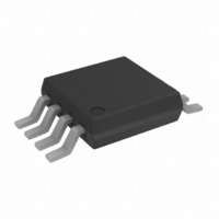
OP2177ARM-R2 Analog Devices Inc, OP2177ARM-R2 Datasheet - Page 16

OP2177ARM-R2
Manufacturer Part Number
OP2177ARM-R2
Description
IC OPAMP GP 1.3MHZ DUAL LN 8MSOP
Manufacturer
Analog Devices Inc
Datasheet
1.OP2177ARZ.pdf
(24 pages)
Specifications of OP2177ARM-R2
Rohs Status
RoHS non-compliant
Design Resources
16-Bit Fully Isolated Voltage Output Module Using AD5662, ADuM1401, and External Amplifiers (CN0063)
Amplifier Type
General Purpose
Number Of Circuits
2
Slew Rate
0.7 V/µs
Gain Bandwidth Product
1.3MHz
Current - Input Bias
500pA
Voltage - Input Offset
15µV
Current - Supply
400µA
Current - Output / Channel
10mA
Voltage - Supply, Single/dual (±)
5 V ~ 36 V, ±2.5 V ~ 18 V
Operating Temperature
-40°C ~ 125°C
Mounting Type
Surface Mount
Package / Case
8-MSOP, Micro8™, 8-uMAX, 8-uSOP,
Output Type
-
-3db Bandwidth
-
Other names
OP2177ARM-R2
OP2177ARM-R2TR
OP2177ARM-R2TR
OP1177/OP2177/OP4177
Figure 18 shows the positive overload recovery time of the
OP1177. The output recovers in less than 4 μs after being
overdriven by more than 100%.
The negative overload recovery of the OP1177 is 1.4 μs, as seen
in Figure 19.
THD + NOISE
The OPx177 has very low total harmonic distortion. This indicates
excellent gain linearity and makes the OPx177 a great choice for
high closed-loop gain precision circuits.
Figure 55 shows that the OPx177 has approximately 0.00025%
distortion in unity gain, the worst-case configuration for distortion.
CAPACITIVE LOAD DRIVE
OPx177 is inherently stable at all gains and capable of driving
large capacitive loads without oscillation. With no external
compensation, the OPx177 safely drives capacitive loads up to
1000 pF in any configuration. As with virtually any amplifier,
driving larger capacitive loads in unity gain requires additional
circuitry to assure stability.
In this case, a snubber network is used to prevent oscillation
and reduce the amount of overshoot. A significant advantage of
this method is that it does not reduce the output swing because
the Resistor R
0.0001
200mV
0.001
0.01
0.1
20
Figure 54. Test Circuit for Overload Recovery Time
+
–
S
is not inside the feedback loop.
1kΩ
R1
Figure 55. THD + N vs. Frequency
100
FREQUENCY (Hz)
2
3
OP1177
100kΩ
R2
7
4
V+
V–
6
1k
V
R
BW = 22kHz
10kΩ
SY
L
= 10kΩ
= ±15V
V
OUT
6k
Rev. G | Page 16 of 24
Figure 56 is a scope shot of the output of the OPx177 in response
to a 400 mV pulse. The load capacitance is 2 nF. The circuit is
configured in positive unity gain, the worst-case condition for
stability.
As shown in Figure 58, placing an R-C network parallel to the
load capacitance (C
of C
There is no ringing, and overshoot is reduced from 27% to 5%
using the snubber network.
Optimum values for R
capacitive loads, up to 200 nF. Values for other capacitive loads can
be determined experimentally.
Table 5. Optimum Values for Capacitive Loads
C
10 nF
50 nF
200 nF
L
L
without causing oscillation or excessive overshoot.
GND
GND
0
Figure 56. Capacitive Load Drive Without Snubber
Figure 57. Capacitive Load Drive with Snubber
L
) allows the amplifier to drive higher values
S
R
20 Ω
30 Ω
200 Ω
and C
S
TIME (10µs/DIV)
TIME (10µs/DIV)
S
are tabulated in Table 5 for several
C
0.33 μF
6.8 nF
0.47 μF
S
V
R
R
C
C
V
R
C
SY
L
S
L
S
SY
L
L
= 10kΩ
= 200Ω
= 2nF
= 0.47µF
= 10kΩ
= 2nF
= ±5V
= ±5V


