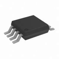
OP2177ARM-R2 Analog Devices Inc, OP2177ARM-R2 Datasheet - Page 20

OP2177ARM-R2
Manufacturer Part Number
OP2177ARM-R2
Description
IC OPAMP GP 1.3MHZ DUAL LN 8MSOP
Manufacturer
Analog Devices Inc
Datasheet
1.OP2177ARZ.pdf
(24 pages)
Specifications of OP2177ARM-R2
Rohs Status
RoHS non-compliant
Design Resources
16-Bit Fully Isolated Voltage Output Module Using AD5662, ADuM1401, and External Amplifiers (CN0063)
Amplifier Type
General Purpose
Number Of Circuits
2
Slew Rate
0.7 V/µs
Gain Bandwidth Product
1.3MHz
Current - Input Bias
500pA
Voltage - Input Offset
15µV
Current - Supply
400µA
Current - Output / Channel
10mA
Voltage - Supply, Single/dual (±)
5 V ~ 36 V, ±2.5 V ~ 18 V
Operating Temperature
-40°C ~ 125°C
Mounting Type
Surface Mount
Package / Case
8-MSOP, Micro8™, 8-uMAX, 8-uSOP,
Output Type
-
-3db Bandwidth
-
Other names
OP2177ARM-R2
OP2177ARM-R2TR
OP2177ARM-R2TR
OP1177/OP2177/OP4177
SINGLE OPERATIONAL AMPLIFIER BRIDGE
The low input offset voltage drift of the OP1177 makes it very
effective for bridge amplifier circuits used in RTD signal condi-
tioning. It is often more economical to use a single bridge
operational amplifier as opposed to an instrumentation amplifier.
In the circuit shown in Figure 66, the output voltage at the
operational amplifier is
0.1µF
V
O
100Ω
RTD
=
ADR421
R2
+15V
R
Figure 65. Low Power Linearized RTD Circuit
⎡
⎢
⎢
⎢
⎢
⎣
V
4.12kΩ
REF
2
3
⎛
⎜
⎜
⎜
⎜
⎝
OP2177
R1
R
100Ω
1/2
8
4
V+
V–
+
⎛ +
⎜
⎝
1
100Ω
4.12kΩ
δ
R2
1
R1
20Ω
⎞
⎟
⎠
(
1
+
V
OUT
δ
4.37kΩ
)
6
5
⎞
⎟
⎟
⎟
⎟
⎠
⎤
⎥
⎥
⎥
⎥
⎦
OP2177
1/2
49.9kΩ
500Ω
200Ω
7
5kΩ
V
Rev. G | Page 20 of 24
OUT
where δ = ΔR/R is the fractional deviation of the RTD resistance
with respect to the bridge resistance due to the change in temper-
ature at the RTD.
For δ << 1, the preceding expression becomes
With V
to δ with a gain factor of
0.1µF
V
V
⎡
⎢
⎣
O
⎛
⎜
⎝
REF
REF
R2
≅
R
⎛
⎜
⎝
constant, the output voltage is linearly proportional
ADR421
⎛
⎜
⎝
⎞
⎟
⎠
R2
R2
R
⎛
⎜
⎝
R
15V
1
⎞
⎟
⎠
+
⎞
⎟
⎠
⎡
⎢
⎣
V
R2
R1
⎛ +
⎜
⎝
Figure 66. Single Bridge Amplifier
1
REF
R(1+δ)
⎞
⎟
⎠
⎛
⎜
⎜
⎜
⎜
⎝
+
R1
R2
1
R
⎛
⎜
⎝
+
R2
⎞
⎟
⎠
R1
+
R1
R
⎛
⎜
⎝
⎞
⎟
⎠
δ
⎤
⎥
⎦
R2
+
R1
R
R
V
R2
R1
REF
⎞
⎟
⎠
⎤
⎥
⎦
δ
⎞
⎟
⎟
⎟
⎟
⎠
=
2
3
OP1177
R
R
7
4
F
V+
V–
F
6
V
OUT


