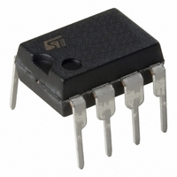
TS1852AIN STMicroelectronics, TS1852AIN Datasheet - Page 13

TS1852AIN
Manufacturer Part Number
TS1852AIN
Description
IC OP AMP DUAL R-R I/O 8-DIP
Manufacturer
STMicroelectronics
Datasheet
1.TS1851IDT.pdf
(24 pages)
Specifications of TS1852AIN
Amplifier Type
General Purpose
Number Of Circuits
2
Output Type
Rail-to-Rail
Slew Rate
0.25 V/µs
Gain Bandwidth Product
630kHz
Current - Input Bias
16nA
Voltage - Input Offset
1000µV
Current - Supply
162µA
Current - Output / Channel
48mA
Voltage - Supply, Single/dual (±)
1.8 V ~ 6 V
Operating Temperature
-40°C ~ 125°C
Mounting Type
Through Hole
Package / Case
8-DIP (0.300", 7.62mm)
Lead Free Status / RoHS Status
Lead free / RoHS Compliant
-3db Bandwidth
-
TS185x, TS185xA
Figure 31. Slew rate vs. temperature at
Figure 33. Phase margin vs. output current
Figure 35. Distortion vs. output voltage at
0.22
0.20
0.19
0.18
0.17
0.16
0.15
0.14
0.13
85
80
75
70
65
60
55
10.000
0.21
1.000
0.100
0.010
0.001
-10
-40
0.000
VCC = 5V
gain = +1
Vin = 2 to 3V
RL = 10kohms
CL = 100 pF
Vcc = 5 V
Vcc = 1.8 V
-20
VCC = 1.8V
f = 1kHz
T = 25°C
gain = -1
0.100
RL = 2kohms
0
-5
DC Output Current (mA)
0.200
Output Voltage (V)
Temperature (°C)
20
0.300
40
0.400
0
positive Slew Rate
60
negative Slew Rate
0.500
80
VCC = 3V
RL = 2 kohms
CL = 100 pF
0.600
RL = 10kohms
5
100
0.700
120
Doc ID 6991 Rev 4
0.800
140
10
Figure 32. Phase margin vs. load capacitor
Figure 34. Equivalent input noise vs.
Figure 36. Distortion vs. output voltage at
-10
50
40
30
20
10
10.000
70
60
50
40
30
20
10
0
1E+1
0
1.000
0.100
0.010
0.001
10
0.000
VCC = 1.8V
gain = 100
Rs = 100 ohms
frequency
Vcc = 3 V
VCC = 3V
f = 1kHz
RL = 10K
T = 25°C
gain = -1
0.200
1E+2
Load Capacitor (pF)
100
Output Voltage (V)
0.400
Frequency (Hz)
Electrical characteristics
1E+3
0.600
1000
0.800
VCC = 3V
gain = -1
1E+4
1.000
1.200
10000
1E+5
13/24


