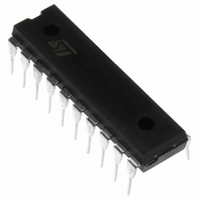
TSM111CN STMicroelectronics, TSM111CN Datasheet - Page 13

TSM111CN
Manufacturer Part Number
TSM111CN
Description
IC SUPERVISOR TRI VOLT&CUR 20DIP
Manufacturer
STMicroelectronics
Type
Multi-Voltage Supervisorr
Datasheet
1.TSM111CDT.pdf
(17 pages)
Specifications of TSM111CN
Number Of Voltages Monitored
3
Reset Timeout
100 ms Minimum
Voltage - Threshold
4V, 6.1V, 14.2V
Operating Temperature
0°C ~ 70°C
Mounting Type
Through Hole
Package / Case
20-DIP (0.300", 7.62mm)
Monitored Voltage
3.3 V, 5 V, 12 V
Undervoltage Threshold
3.8 V, 5.8 V, 13.4 V
Manual Reset
Not Resettable
Watchdog
No Watchdog
Supply Voltage (max)
36 V
Supply Voltage (min)
14.5 V
Supply Current (typ)
5000 uA
Maximum Power Dissipation
1000 mW
Maximum Operating Temperature
+ 70 C
Mounting Style
Through Hole
Minimum Operating Temperature
0 C
Lead Free Status / RoHS Status
Lead free / RoHS Compliant
Output
-
Reset
-
Lead Free Status / Rohs Status
Lead free / RoHS Compliant
Other names
497-2334-5
Available stocks
Company
Part Number
Manufacturer
Quantity
Price
Part Number:
TSM111CN
Manufacturer:
ST
Quantity:
20 000
EVALUATION BOARD - TECHNICAL NOTE
TSM111 is a Housekeeping IC which is best used
in PC Switch Mode Power Supplies for secondary
3.3V, 5V, and 12V power lines protection.
TSM111 integrates all the necessary functions for
a secure and reliable overcurrent and overvoltage
protection, as well as a logic interface for proper
communication with the motherboard and adjust-
able timing circuitry for optimized sequencing
management. Moreover, TSM111 integrates two
precise shunt voltage references for direct opto-
coupler drive. TSM111, integrating the equivalent
of more than 25 discrete components, saves a lot
of design time and fine tuning, as well as PCB ar-
ea, and increases the reliability of the whole appli-
cation.
How to use the TSM111 Evaluation Board ?
This evaluation board allows to adapt the TSM111
housekeeping chip to an already existing PC Pow-
er Supply by simply choosing proper values for it’s
external components, and making the adequate
connections to the I/O of the evaluation board.
The Electrical Schematic of the TSM111 evalua-
tion board is shown on figure 1. It includes the
TSM111 as well as the minimum component num-
ber required to make the TSM111 fit in a PC
SMPS application.
Components calculations
The overvoltage protection is not to be adjusted.
Internal voltage thresholds are given by Vvs1,
Vvs2, Vvs3 for respective protection of the 3.3V,
5V, 12V power lines.
The overcurrent protection is given by the choice
of the Sense resistors R1, R2, R3 (respectively for
each power line 3.3V, 5V, 12V). Internal precise
voltage thresholds define the tripping voltage
drops for each line following equations 1, 2 & 3 :
Vcs1 = R1 x I33
Vcs2 = R2 x I5
Vcs3 = R3 x I12
where I33, I5, and I12 are the tripping currents.
The system will latch (Fault output will be active -
high) if the overcurrent lasts more than the autho-
rized surge delay Tsur given by equations 4 & 5 :
Icharge = Vcc / R4
Tsur = (C1 x Vsur) / Icharge
Note that eq4 is an approximation of a capacitive
charge where Vcc (16V min) is large versus the
threshold voltage Vsur (2.5V).
R4=33k , C1=4.7 F => Tsur=21ms
Thanks to the Tsur adjustment, the normal surge
currents which occur during power up (capacitive
oads charging) are blanked for a time depending
on each application.
eq1
eq2
eq3
eq4
eq5
TSM111
13/17


