ADP125ARHZ-R7 Analog Devices Inc, ADP125ARHZ-R7 Datasheet - Page 14
ADP125ARHZ-R7
Manufacturer Part Number
ADP125ARHZ-R7
Description
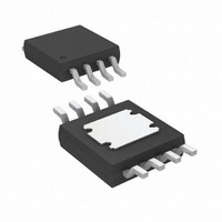
IC REG LDO ADJ 500MA 8MSOP
Manufacturer
Analog Devices Inc
Specifications of ADP125ARHZ-R7
Regulator Topology
Positive Adjustable
Voltage - Output
0.8 ~ 5 V
Voltage - Input
2.3 ~ 5.5 V
Voltage - Dropout (typical)
0.13V @ 500mA
Number Of Regulators
1
Current - Output
500mA (Max)
Current - Limit (min)
550mA
Operating Temperature
-40°C ~ 85°C
Mounting Type
Surface Mount
Package / Case
8-MSOP Exposed Pad, 8-HMSOP, 8-eMSOP
Primary Input Voltage
5.5V
Output Voltage Adjustable Range
800mV To 5V
Dropout Voltage Vdo
130mV
No. Of Pins
8
Output Current
500mA
Voltage Regulator Case Style
MSOP
Operating Temperature Range
-40°C
Lead Free Status / RoHS Status
Lead free / RoHS Compliant
Other names
ADP125ARHZ-R7TR


ADP124/ADP125
CURRENT LIMIT AND THERMAL OVERLOAD
PROTECTION
The ADP124/ADP125 are protected from damage due to excessive
power dissipation by current and thermal overload protection
circuits. The ADP124/ADP125 are designed to limit the current
when the output load reaches 750 mA (typical). When the output
load exceeds 750 mA, the output voltage is reduced to maintain
a constant current limit.
Thermal overload protection is included, which limits the junction
temperature to a maximum of 150°C typical. Under extreme con-
ditions (that is, high ambient temperature and power dissipation),
when the junction temperature starts to rise above 150°C, the
output is turned off, reducing output current to zero. When the
junction temperature cools to less than 135°C, the output is turned
on again and the output current is restored to its nominal value.
Consider the case where a hard short from VOUT to GND occurs.
At first, the ADP124/ADP125 limit the current so that only 750 mA
is conducted into the short. If self-heating causes the junction
temperature to rise above 150°C, thermal shutdown activates,
turning off the output and reducing the output current to zero.
When the junction temperature cools to less than 135°C, the
output turns on and conducts 750 mA into the short, again
causing the junction temperature to rise above 150°C. This
thermal oscillation between 135°C and 150°C results in a current
oscillation between 750 mA and 0 mA that continues as long
as the short remains at the output.
Current and thermal limit protections are intended to protect the
device from damage due to accidental overload conditions. For
reliable operation, the device power dissipation must be externally
limited so that the junction temperature does not exceed 125°C.
THERMAL CONSIDERATIONS
To guarantee reliable operation, the junction temperature of the
ADP124/ADP125 must not exceed 125°C. To ensure that the
junction temperature is less than this maximum value, the user
needs to be aware of the parameters that contribute to junction
temperature changes. These parameters include ambient tem-
perature, power dissipation in the power device, and thermal
resistances between the junction and ambient air (θ
of θ
and the amount of copper to which the GND pins of the package
are soldered on the PCB. Table 6 shows typical θ
8-lead MSOP package for various PCB copper sizes. Table 7
shows typical Ψ
3 mm LFCSP package.
JA
is dependent on the package assembly compounds used
JB
values of the 8-lead MSOP and 8-lead 3 mm ×
JA
JA
values of the
). The value
Rev. A | Page 14 of 20
Table 6. Typical θ
Table 7. Typical Ψ
MSOP
31.7
The junction temperature of the ADP124/ADP125 can be
calculated from the following equation:
where:
T
P
where:
I
I
V
The power dissipation due to ground current is quite small and
can be ignored. Therefore, the junction temperature equation
can be simplified as follows:
As shown in Equation 4, for a given ambient temperature, input-
to-output voltage differential, and continuous load current, there
exists a minimum copper size requirement for the PCB to ensure
that the junction temperature does not rise above 125°C. Figure 36
through Figure 41 show junction temperature calculations for
different ambient temperatures, load currents, V
differentials, and areas of PCB copper.
In cases where the board temperature is known, the thermal
characterization parameter, Ψ
ction temperature rise. The maximum junction temperature (T
calculated from the board temperature (T
(P
LOAD
GND
Copper
Size (mm
25
100
500
1000
6400
D
A
IN
D
is the ambient temperature.
is the power dissipation in the die, given by
) using the formula
and V
is the ground current.
T
P
T
T
is the load current.
D
J
J
J
= T
= T
= T
= [(V
OUT
A
A
B
2
)
+ (P
+ (P
+ {[(V
IN
are input and output voltages, respectively.
− V
MSOP
108.6
75.5
42.5
34.7
26.1
D
D
× Ψ
× θ
JA
IN
OUT
JB
Values for Specified PCB Copper Sizes
− V
Values
JA
) × I
JB
)
)
OUT
LOAD
Ψ
) × I
θ
JB
JB
JA
] + (V
(°C/W)
, can be used to estimate the jun-
(°C/W)
LOAD
LFCSP
44.1
] × θ
IN
× I
B
JA
) and power dissipation
GND
}
LFCSP
177.8
138.2
79.8
67.8
53.5
)
IN
to V
OUT
J
) is
(2)
(3)
(4)
(5)
Related parts for ADP125ARHZ-R7
Image
Part Number
Description
Manufacturer
Datasheet
Request
R

Part Number:
Description:
±1.7g Dual-Axis IMEMS Accelerometer Evaluation Board
Manufacturer:
Analog Devices Inc
Datasheet:

Part Number:
Description:
Inertial Sensor Evaluation System
Manufacturer:
Analog Devices Inc
Datasheet:
Part Number:
Description:
Manufacturer:
Analog Devices Inc
Datasheet:
Part Number:
Description:
Manufacturer:
Analog Devices Inc
Datasheet:
Part Number:
Description:
Manufacturer:
Analog Devices Inc
Datasheet:
Part Number:
Description:
Manufacturer:
Analog Devices Inc
Datasheet:
Part Number:
Description:
Manufacturer:
Analog Devices Inc
Datasheet:
Part Number:
Description:
Manufacturer:
Analog Devices Inc
Datasheet:
Part Number:
Description:
Manufacturer:
Analog Devices Inc
Datasheet:
Part Number:
Description:
Manufacturer:
Analog Devices Inc
Datasheet:
Part Number:
Description:
Manufacturer:
Analog Devices Inc
Datasheet:
Part Number:
Description:
Manufacturer:
Analog Devices Inc
Datasheet:
Part Number:
Description:
Manufacturer:
Analog Devices Inc
Datasheet: