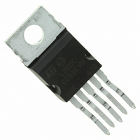
L200CV STMicroelectronics, L200CV Datasheet

L200CV
Specifications of L200CV
Available stocks
Related parts for L200CV
L200CV Summary of contents
Page 1
ADJUSTABLE VOLTAGE AND CURRENT REGULATOR ADJUSTABLE OUTPUT CURRENT (GUARANTEED 150 C) j ADJUSTABLE OUTPUT VOLTAGE DOWN TO 2.85 V INPUT OVERVOLTAGE PROTECTION ( ms) SHORT CIRCUIT PROTECTION ...
Page 2
L200 CONNECTION DIAGRAMS AND ORDER CODES (top views) Type L200 L200 C BLOCK DIAGRAM APPLICATION CIRCUITS Figure 1. Programmable Voltage Regulator with Current Limiting 2/12 ® Pentawatt L200 CH L200 CV Figure 2. Programmable Current Regulator. TO-3 L200 T L200 ...
Page 3
SCHEMATIC DIAGRAM ELECTRICAL CHARACTERISTICS (T Symbol Parameter VOLTAGE REGULATION LOOP I Quiescent drain Current (pin Output Noise Voltage N V Output Voltage Range o V Voltage Load Regulation o (note Line Regulation i ...
Page 4
L200 ELECTRICAL CHARACTERISTICS (continued) Symbol Parameter Average Temperature Coefficient V ref of Reference Voltage I Bias Current and Pin 4 4 Average Temperature Coefficient (pin Output Impedance o CURRENT REGULATION LOOP V Current ...
Page 5
Figure 5. Quiescent Current vs. Junction Voltage. Figure 7. Output Noise Voltage vs. Output Voltage. Figure 9. Reference Voltage vs. Junction Temperature. Figure 6. Quiescent Current vs. Output Current. Figure 8. Output Noise Voltage vs. Frequency. Figure 10. Voltage Load ...
Page 6
L200 Figure 11. Supply Voltage Rejection vs. Frequency ure tpu t Imped ance vs. Frequency. Figure 15. Voltage Transient Reponse. 6/12 Figure 12. Dropout Voltage vs. Junction Temperature. Figure 14. Output Impedance vs. Output Current. ...
Page 7
Figure 17. Load Transient Reponse APPLICATIONS CIRCUITS Figure 19. - Programmable Voltage Regulator Figure 21. - High Current Voltage Regulator with Short Circuit Protection. Figure 18. Current Limit Sense Voltage vs. Junction Temperature. Figure 20. - P.C. Board and Components ...
Page 8
L200 Figure 23. Programmable Voltage and Current Regulator. Note: Connecting point negative voltage (for example - 3V/10 mA possible to extend the output voltage range down and obtain the current limiting down ...
Page 9
Figure 26. High Input and Output Voltage. Figure 28 Motor Speed Control. Figure 27. Constant Current Battery Charger. The resistors R and R determine the final charging volt age and R the initial charging current. D ...
Page 10
L200 mm DIM. MIN. TYP. MAX. A 4.8 C 1.37 D 2.4 2.8 0.094 D1 1.2 1.35 0.047 E 0.35 0.55 0.014 E1 0.76 1.19 0.030 F 0.8 1.05 0.031 F1 1 1.4 0.039 G 3.2 3.4 3.6 0.126 G1 ...
Page 11
DIM. MIN. TYP. MAX. MIN. A 11.8 B (*) 1 0.39 C 2 (typ (typ.) P 26.2 R 3.88 4.20 0.15 U 39.5 V 30.1 (*) Measured with Gauge ...
Page 12
... No license is granted by implication or otherwise under any patent or patent rights of STMicroelectronics. Specification mentioned in this publication are subject to change without notice. This publication supersedes and replaces all information previously supplied. STMicroelectronics products are not authorized for use as critical components in life support devices or systems without express written approval of STMicroelectronics ...


