BH30RB1WGUT-E2 Rohm Semiconductor, BH30RB1WGUT-E2 Datasheet - Page 2
BH30RB1WGUT-E2
Manufacturer Part Number
BH30RB1WGUT-E2
Description
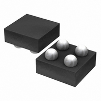
IC REG LDO 3.0V 150MA 4-VCSP
Manufacturer
Rohm Semiconductor
Specifications of BH30RB1WGUT-E2
Regulator Topology
Positive Fixed
Voltage - Output
3V
Voltage - Input
Up to 5.5V
Voltage - Dropout (typical)
0.1V @ 100mA
Number Of Regulators
1
Current - Output
150mA (Max)
Operating Temperature
-40°C ~ 85°C
Mounting Type
Surface Mount
Package / Case
4-VCSP
Primary Input Voltage
4V
Output Voltage
3V
Dropout Voltage Vdo
25mV
No. Of Pins
4
Output Current
150mA
Voltage Regulator Case Style
VCSP
Operating Temperature Range
-40°C To +85°C
Svhc
No
Number Of Outputs
1
Polarity
Positive
Input Voltage Max
5.5 V
Output Type
Fixed
Dropout Voltage (max)
150 mV
Line Regulation
20 mV
Load Regulation
2 mV
Voltage Regulation Accuracy
1 %
Maximum Power Dissipation
0.53 W
Maximum Operating Temperature
+ 85 C
Mounting Style
SMD/SMT
Minimum Operating Temperature
- 40 C
Output Voltage Fixed
3V
Rohs Compliant
Yes
Lead Free Status / RoHS Status
Lead free / RoHS Compliant
Current - Limit (min)
-
Lead Free Status / Rohs Status
Lead free / RoHS Compliant
Other names
BH30RB1WGUT-E2TR
Available stocks
Company
Part Number
Manufacturer
Quantity
Price
Company:

Part Number:
BH30RB1WGUT-E2
Manufacturer:
ROHM
Quantity:
3 000


●Absolute maximum ratings
●Recommended operating ranges (not to exceed Pd)
●Recommended operating conditions
●Electrical characteristics
© 2011 ROHM Co., Ltd. All rights reserved.
BH□□RB1WGUT series
www.rohm.com
(Unless otherwise specified, Ta = 25°C, V
Applied supply voltage
Power dissipation
Operating temperature range
Storage temperature range
*1: Reduce by 5.3 mW/C over 25C, when mounted on a glass epoxy PCB (7 mm 7 mm 0.8 mm).
Power supply voltage
Output current
Input capacitor
Output capacitor
*2: Make sure that the output capacitor value is not kept lower than this specified level across a variety of temperature, DC bias characteristic.
Output voltage 1
Output voltage 2
Circuit current
Circuit current (STBY)
Ripple rejection ratio
Dropout voltage
Line regulation
Load regulation
Overcurrent protection limit current
Short current
STBY pin current
STBY control voltage
* This IC is not designed to be radiation-resistant.
*3: These specifications are guaranteed by design.
*4: For BH15, 18RB1WGUT, VIN = 3.0 V to 5.5 V.
*5: For BH15, 18RB1WGUT, VIN = 3.5 V.
And also make sure that the capacitor value cannot change as time progresses.
Parameter
Parameter
Parameter
Parameter
OFF
ON
ISHORT
Symbol
Symbol
Symbol
Symbol
VSTBH
VSTBL
ICCST
ILMAX
VMAX
V
V
ISTBY
VDLO
VSAT
IGND
IOUT
VDLI
Topr
Tstg
C
OUT
OUT
V
RR
Pd
C
IN
IN
IN
O
= V
1
2
OUT
- 25 mV
0.99
0.97
V
V
V
0.7
0.7
Min.
Min.
-0.2
0.5
1.2
OUT
OUT
OUT
—
—
—
—
—
—
—
—
+ 1.0 V
*2
*2
-0.3 to +6.5
-55 to +125
-40 to +85
2.5 to 5.5
0 to 150
Ratings
Ratings
Ratings
Limits
530
V
V
Typ.
*5
Typ.
100
300
1.0
1.0
1.3
34
63
40
OUT
OUT
—
—
—
, STBY = 1.5 V, C
2
2
2/8
*1
+ 25 mV
1.01
1.03
V
V
V
Max.
Max.
150
V
1.0
3.6
0.2
72
—
20
30
—
—
OUT
OUT
OUT
—
—
IN
Unit
mW
Unit
Unit
Unit
mA
mV
mV
mV
mA
mA
°C
µF
µF
µA
µA
dB
µA
°C
IN
V
V
V
V
V
V
= 1 µF, C
The use of ceramic capacitors is
recommended.
The use of ceramic capacitors is
recommended.
I
BH25RB1WGUT or higher
I
BH15, 18RB1WGUT
I
Ta = -40°C to 85°C
I
Ta = -40°C to 85°C
STBY = 0 V
VRR = -20 dBV, fRR = 1 kHz,
I
V
(Excluding BH15, 18RB1WGUT)
I
V
I
V
V
Ta = -40°C to 85°C
Ta = -40°C to 85°C
Ta = -40°C to 85°C
OUT
OUT
OUT
OUT
OUT
OUT
OUT
IN
IN
O
O
= V
= 0 V
= 0.98 V
= V
O
= 1 mA, Ta = 25°C,
= 1mA, Ta = 25°C,
= 1 mA
= 0 mA
= 10 mA
= 10 mA
= 1 mA to 100 mA
= 1 µF)
OUT
OUT
0.98
Conditions
Conditions
+ 0.5 V to 5.5 V
OUT
, I
Technical Note
2011.01 - Rev.C
*3
*3
*3
*3
*3
OUT
= 100 mA
*4
Related parts for BH30RB1WGUT-E2
Image
Part Number
Description
Manufacturer
Datasheet
Request
R

Part Number:
Description:
Manufacturer:
Rohm Semiconductor
Datasheet:
Part Number:
Description:
Manufacturer:
Rohm Semiconductor
Datasheet:
Part Number:
Description:
Manufacturer:
Rohm Semiconductor
Datasheet:
Part Number:
Description:
Manufacturer:
Rohm Semiconductor
Datasheet:
Part Number:
Description:
Manufacturer:
Rohm Semiconductor
Datasheet:
Part Number:
Description:
Manufacturer:
Rohm Semiconductor
Datasheet:
Part Number:
Description:
Manufacturer:
Rohm Semiconductor
Datasheet:
Part Number:
Description:
Manufacturer:
Rohm Semiconductor
Datasheet:
Part Number:
Description:
Manufacturer:
Rohm Semiconductor
Datasheet:
Part Number:
Description:
Manufacturer:
Rohm Semiconductor
Datasheet:
Part Number:
Description:
Manufacturer:
Rohm Semiconductor
Datasheet:
Part Number:
Description:
Manufacturer:
Rohm Semiconductor
Datasheet:

Part Number:
Description:
DIODE SWITCH 80V 25MA SMD5 TR
Manufacturer:
Rohm Semiconductor
Datasheet: