BA50BC0WT Rohm Semiconductor, BA50BC0WT Datasheet - Page 5
BA50BC0WT
Manufacturer Part Number
BA50BC0WT
Description
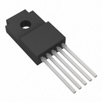
IC REG LDO 1A 5V SHTDN TO220FP-5
Manufacturer
Rohm Semiconductor
Specifications of BA50BC0WT
Regulator Topology
Positive Fixed
Voltage - Output
5V
Voltage - Input
Up to 16V
Voltage - Dropout (typical)
0.3V @ 500mA
Number Of Regulators
1
Current - Output
1A (Max)
Current - Limit (min)
1A
Operating Temperature
-40°C ~ 105°C
Mounting Type
Through Hole
Package / Case
TO-220-5 Full Pack (Straight Leads)
Number Of Outputs
1
Polarity
Positive
Input Voltage Max
16 V
Output Voltage
5 V
Output Type
Fixed
Dropout Voltage (max)
0.5 V at 500 mA
Output Current
1 A
Line Regulation
35 mV
Load Regulation
75 mV
Voltage Regulation Accuracy
2 %
Maximum Power Dissipation
2 W
Maximum Operating Temperature
+ 105 C
Mounting Style
Through Hole
Minimum Operating Temperature
- 40 C
Lead Free Status / RoHS Status
Lead free / RoHS Compliant
Available stocks
Company
Part Number
Manufacturer
Quantity
Price
Company:

Part Number:
BA50BC0WT
Manufacturer:
WINBOND
Quantity:
31 000
Part Number:
BA50BC0WT
Manufacturer:
ROHM/罗姆
Quantity:
20 000


Input / Output Equivalent Circuit Diagrams
Thermal Derating Curves
© 2010 ROHM Co., Ltd. All rights reserved.
BA□□BC0 Series,BA□□BC0W Series,BA00BC0W Series
www.rohm.com
The characteristics of the IC are greatly influenced by the operating temperature. If the temperature exceeds the maximum
junction temperature T
dissipation is within the permissible range in order to prevent instantaneous damage resulting from heat and maintain the
reliability of the IC for long-term operation.
The following method is used to calculate the power consumption Pc (W).
The load current Io is calculated:
Calculation Example:
Vcc = 6.0 V and Vo = 5.0 V at Ta = 85°C
Refer to the above and implement proper thermal designs so that the IC will not be used under excessive power dissipation
conditions under the entire operating temperature range.
The power consumption Pc of the IC in the event of shorting (i.e. the Vo and GND pins are shorted) can be obtained from the
following equation:
Pc = Vcc (Icca + Ishort) (Ishort: short current).
Pc = (Vcc – Vo) Io + Vcc Icca
Vcc
CTL
Power dissipation Pd ≥ Pc
10
25
15
20
5
0
Io ≤ 550 mA (Icca 20 mA)
Io ≤
TO220FP-3/TO220FP-5/TO220FP-5V5)
0
(1)20.0
(2)2.0
AMBIENT TEMPERATURE:Ta [
0.676 − 6.0 Icca
Pd − Vcc Icca
25
Fig.16
Vcc − Vo
6.0 − 5.0
(1) When using an infinite heat sink.
(2) During IC without heat sink operation.
27k Ω
j-c = 6.25 (°C/W)
j-a = 62.5 (°C/W)
jmax
50
Fig.18
, deterioration or damage may occur. Implement proper thermal designs to ensure that power
31k Ω
2k Ω
75
100
125
°C
Fig.17
]
R2
R1
150
Vcc
5/8
ja = 96.2°C/W → −10.4 mW/°C
25°C = 1300 mW → 85°C = 676 mW
1.2
0.8
1.6
0.4
2.0
0
0
OUT
TO252-3/TO252-5
1.30
AMBIENT TEMPERATURE:Ta [
* For the BA00BC0WT, connect R1 and
Equation: VOUT = Vc (R1 + R2) / R1
(Vc = 1.25 V (Typ.))
The recommended R1 value is
approximately 30 k to 150 k.
R2 externally between the C and GND
pins and between the OUT and C pins.
25
IC mounted on a ROHM standard board
Board size: 70 70 1.6 mm
Copper foil area: 7 7 mm
TO252-5 ja=96.2 (°C/W)
TO252-3 ja=104.2 (°C/W)
50
TO252-3
Vcc : Input voltage
Vo
IO
Icca : Circuit current
Fig.19
75
: Output current
: Load current
TO252-5
100
Technical Note
2010.02 - Rev.B
°C
125
]
150
Related parts for BA50BC0WT
Image
Part Number
Description
Manufacturer
Datasheet
Request
R

Part Number:
Description:
Manufacturer:
Rohm Semiconductor
Datasheet:
Part Number:
Description:
Manufacturer:
Rohm Semiconductor
Datasheet:
Part Number:
Description:
Manufacturer:
Rohm Semiconductor
Datasheet:
Part Number:
Description:
Manufacturer:
Rohm Semiconductor
Datasheet:
Part Number:
Description:
Manufacturer:
Rohm Semiconductor
Datasheet:
Part Number:
Description:
Manufacturer:
Rohm Semiconductor
Datasheet:
Part Number:
Description:
Manufacturer:
Rohm Semiconductor
Datasheet:
Part Number:
Description:
Manufacturer:
Rohm Semiconductor
Datasheet:
Part Number:
Description:
Manufacturer:
Rohm Semiconductor
Datasheet:
Part Number:
Description:
Manufacturer:
Rohm Semiconductor
Datasheet:
Part Number:
Description:
Manufacturer:
Rohm Semiconductor
Datasheet:
Part Number:
Description:
Manufacturer:
Rohm Semiconductor
Datasheet:

Part Number:
Description:
DIODE SWITCH 80V 25MA SMD5 TR
Manufacturer:
Rohm Semiconductor
Datasheet: